Stock Yard Panel Layout

Previous Topic Next Topic
 
classic Classic list List threaded Threaded
13 messages Options
Reply | Threaded
Open this post in threaded view
|

Stock Yard Panel Layout

flywire
This post was updated on .
What is the best way to layout fence panels from a few standard panel lengths for stock yards? The fence has many yards with straight and arc sections, and each panel (say 2m, 2.4m, 3m) has to join the next.

With complex shapes, it is not really feasible to just use blocks and snap the ends together. I'm thinking I could draw the basic layout, for example, a rectangle with a semicircle on one end as a guide layer then snap the panels to the shape. Ideally, one panel could be selected and after changing the length the position of the others would update.

Any thoughts?
Reply | Threaded
Open this post in threaded view
|

Re: Stock Yard Panel Layout

dxli
I am not clear on the details, but using "straight and arc sections" reminds me about polylines.

I didn't work on polylines much, but the basic:

1, it's connected;
2, each segment you can choose line or arc;
3, for each arc, you can choose tangent or not.

Try the Polyline button or menu: Tools > Polyline > Polyline.

Hatching works for a polyline contour, so you should be able find the total area of a contour easily by hatching. The total area is printed to the Command Line tool.

flywire wrote
What is the best way to layout fence panels from a few standard panel lengths for stock yards? The fence has many yards with straight and arc sections, and each panel (say 2m, 2.4m, 3m) has to join the next.

With complex shapes, it is not really feasible to just use blocks and snap the ends together. I'm thinking I could draw the basic layout, for example, a rectangle with a semicircle on one end as a guide layer then snap the panels to the shape. Ideally, one panel could be selected and after changing the length the position of the others would update.

Any thoughts?
Reply | Threaded
Open this post in threaded view
|

Re: Stock Yard Panel Layout

flywire
Thank you @dxli, that is pretty well the process I used. There are a few things I'd like to follow up.

I'll describe https://www.dpi.nsw.gov.au/__data/assets/pdf_file/0020/343334/Weean-cattle-yards.pdf#page=2 using https://tools.pdf24.org/en/ to Extract PDF image  
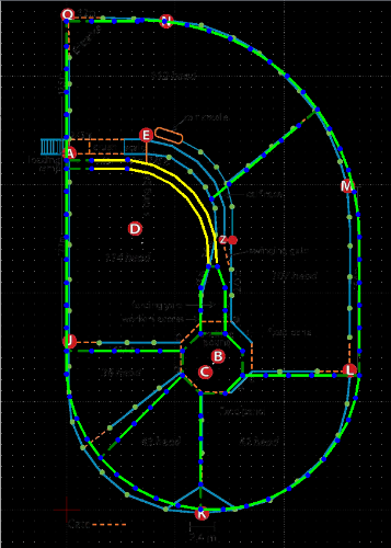
Weean-cattle-yards-2.png as a background image imported to -3.5,-3 (Metres) Scale 0.0305882 and order set to back. (The image is a little hard to read so I used one saved in B&W with a white background although grey on white would have been better.)

This layout is fairly simple as it is based on a semi-circle on the bottom with a quarter circle at the top joined with straight lines. Those panel sizes aren't available so I reworked it to 2.1m panels with 2.3m and 0.8m gates. Steel has minimal tolerances but in some places the fence alignment can be moved without affecting functionality, but other places such as the two long panels in the octagon in the center or outside of the race require manufacturing.


PanelLayoutCadV2.dxf

Some queries:
1. When the background image is turned on it is displayed and selected so clicking the window hides the other layers. Can the layers be worked on with the image visible in the background?
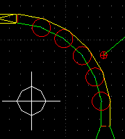
2. Fixed Side length polygons seem to require manual calculation with a tool like https://www.omnicalculator.com/math/regular-polygon to determine the Circumcircle radius/number of Sides before creating the polygon then rotating it or the angle for the first polygon side before rotating multiple copies. Is there an easier way?
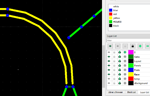
3. The rotate tool seems to require a known angle for rotation. Can rotate be used with snap? I'd like to snap the race between the posts at each end. Image below shows the gap at the bottom above the posts.
4. Horizontal and Vertical panel lines are easily created. Is there an easy way to create angled panel lines like that shown on the top right-hand area between the outside fence and the race?
5. Can a point layer be created from all selected nodes instead of selecting and creating one at a time?
6. How does the divide tool work?

Rotate snap issue
Reply | Threaded
Open this post in threaded view
|

Re: Stock Yard Panel Layout

flywire
This post was updated on .
flywire wrote
4. ...Is there an easy way to create angled panel lines like that shown on the top right-hand area between the outside fence and the race?
Once the polygon parameters are calculated, Line, Relative angle can be used but it is buggy. The line created is double the length given with the midpoint at the specified position (requiring a Divide to fix it). It should work similarly to Angle.

flywire wrote
6. How does the divide tool work?
LordOfBikes wrote
The Divide tool, as its name says, is to divide a single entity into two. link
This is clearer. It would be useful if it supported an array of cut locations.
Reply | Threaded
Open this post in threaded view
|

Re: Stock Yard Panel Layout

dxli
1, to keep the image visible at background: create a new layer; insert an image to the layer; Menu: Tools > Order > Move to Bottom;
2, We have a few methods to draw regular polygons, under: Tools > Line;
3, Rotation can be done by selecting: center, reference point and target point, similar to Copy/Move;
4, Divide (cut) only works for one entity at a time. It's interesting to create a new tool to do fast cutting/trimming. 1. select entities to cut/trim; 2. select an entity so all entities selected in step 1 will be cut but the intersections
Reply | Threaded
Open this post in threaded view
|

Re: Stock Yard Panel Layout

dellus
This post was updated on .
In reply to this post by flywire
'1. When the background image is turned on it is displayed and selected so clicking the window hides the other layers. Can the layers be worked on with the image visible in the background? '

This is an ever since issue, hampering effective use of an image as drawing background.
If you click on a line always the image is selected, if the image layer is locked, nothing can be selected.
Two workarounds which sometimes help, depending on the kind of operation:
-Select the drawing entity by pulling up a window around it.
-Switch off the image layer for selecting an entity, switch it on again during the operation and specify, for example, reference and target point.

@dxli: if you decide to work on this you might at that occasion also have a look at https://github.com/LibreCAD/LibreCAD/issues/1258

Edit: OK, I may have misinterpreted flywire's query, Dxli's answer is correct if it's just about the image hiding the drawing. Still, the issue I am talking of remains.
Reply | Threaded
Open this post in threaded view
|

Re: Stock Yard Panel Layout

flywire
This post was updated on .
In reply to this post by dxli
dxli wrote
1, to keep the image visible at background: create a new layer; insert an image to the layer; Menu: Tools > Order > Move to Bottom;
Seems exactly as described in my post (the image with layers shows it is a separate layer). The issue is regardless of setting the order to the bottom, in use entities are drawn over the image but the order is clearly at the top (ie other objects can't be selected over the image area while it is visible if they don't extend past the image) and seems to be consistent with @dellus comments (ie can't change the entities and view the image under it at the same time). Feel free to check the attached file. Did I miss something in the @dellus edit?

I take it that there are no magic bullet solutions to those queries. I'd particularly like a workaround for point 3 (rotate snap) which I haven't resolved.
Reply | Threaded
Open this post in threaded view
|

Re: Stock Yard Panel Layout

dellus
This post was updated on .
I don't have the time to check it thoroughly at the moment, as I am about to leave the house, but I think you can just ignore the angle setting in the box when rotating if you specify it by snap, works for me. It always shows the last resulting angle.

Edit: Nonsense. Of course it does not show the last resulting angle (from previous operation), but the angle resulting from using snap. Confusing is that if you want a certain angle value, you have to specify a target point first and then overwrite the indicated value in the input field.
 
Reply | Threaded
Open this post in threaded view
|

Re: Stock Yard Panel Layout

flywire
https://www.youtube.com/shorts/1KQlt0Gp_hI

Dumb user error, selecting Rotation point then the same Reference point (as with copy/move) suppresses the Target point to rotate to prompt. LC should generate an error when this occurs.
Reply | Threaded
Open this post in threaded view
|

Re: Stock Yard Panel Layout

flywire
Well, that didn't fix my issue. How can I make the polyline longer and narrower retaining the segment lengths?
Reply | Threaded
Open this post in threaded view
|

Re: Stock Yard Panel Layout

dxli
In reply to this post by dellus
I will try this one.

dellus wrote
@dxli: if you decide to work on this you might at that occasion also have a look at https://github.com/LibreCAD/LibreCAD/issues/1258
Reply | Threaded
Open this post in threaded view
|

Re: Stock Yard Panel Layout

flywire
In reply to this post by flywire
flywire wrote
How can I make the polyline longer and narrower retaining the segment lengths?
I don't think it can be calculated. I understand it needs to be determined by iteration.
Reply | Threaded
Open this post in threaded view
|

Re: Stock Yard Panel Layout

flywire


The ends of the race are at 90° so after the inner arc is adjusted manually the outer arc needs to be calculated manually. Each 2.1m long panel in the race is joined by an 0.8m wide by 0.1m long bow. Construction lines between each panel and the ends of the race allow the outer race to be drawn and the length split between the required panels.

By chance, the answer is close enough to a standard 2.3m panel. The panels can be rotated and snapped into place using the construction lines.