Difficulty changing line width
|
I'm not able to change the line width of an existing line through the Tools/Modify/Properties dialog. The problem is similar to what is described at http://forum.librecad.org/Line-Width-Does-Not-Show-td5712001i20.html, but the resolution there does not work.
Description: I have an existing drawing in which I am trying to change the properties of a continuous line to a thicker width. I can change the color or the line type successfully, but when I change the line width, it remains a very thin line. I am not in draft mode. I have tried simply drawing a line in a new file, and I have the same experience. Installation: Version 2.1.3, running under Windows 7, 64 bit.. I uninstalled and reinstalled LC, but that didn't solve the problem. I'm a new user, so my apologies if I'm missing something obvious. And, thanks to other users who have answered some of my neophyte questions already, which has been quite helpful Regards, Mike |
|
Let's make a test:
Make sure your units are mm. Should be by default. Set line width to 0.5 mm. Draw a line not too long in comparison to the width, so let's say about 10 to 15 mm. Zoom in or autozoom. Still a thin line? |
|
Aha, and thanks for your help. I changed "Main drawing unit" to mm under "Drawing Preferences," and my Length Format to Scientific. Now, yes, the line shows as thick. When I change the "Main Drawing Unit" back to "Inch," the line appears as thin. In the current application, I'm wanting to do some floorplan drawings for my house, for which inches would make sense. I guess I don't understand what to do if I want Architectural for my Length Format, which LC does not accept as consistent with mm for the Main Drawing Unit. Does this length format not allow differing line thicknesses, or what's going on?
Thanks, Mike |
|
In drawing mode LC shows line width in "real" size, for instance 0.5 mm like drawn with a 0.5 mm thick pen on the ground. Compared to the size of a house they will appear very thin. Still, if you zoom in very close you will see a thickness. A (printed or handdrawn) house plan will have a scale, for instance 1:100, and in relation to that scaled down size the lines will appear as thick as expected as the line width will not be scaled down. So check the appearance in print preview mode, be sure to have set proper scale and paper size.
With inches and architectural units things are getting more complicated. As I am German I don't have much understanding of this and can't help you much. Maybe you can develop into a master in these things and guide others. |
Re: Difficulty changing line width
|
I found this thread helpful, as I was having the same difficulty.
However, I still have a problem. I can change the line thickness up to .5 mm and see a change. However, if I change it to any figure up to that, it makes no difference. For example, if I change it to .25mm, it does not change. Also, when I export the file in a .jpg format, it is still thin. My purpose in this instance is to arrive at a .jpg file that can be posted on another forum to be read by others with a line thickness large enough to be easily read. So far, I have not been able to achieve this. I have been able to export a file and post it, but the result is very faint. Please advise further. |
|
I cannot reproduce this, it works for me.
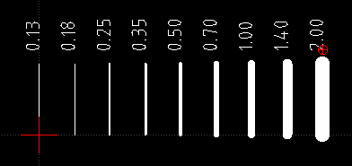
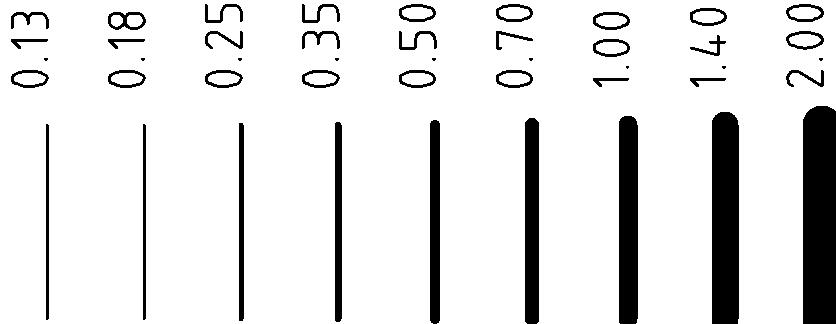
linetest.dxf   As it is difficult to impossible to completely control the result of "export as image" I recommend to make a pdf of the plan first. So go into print preview and make your setting as if you would want to print to paper (don't forget to set the proper paper size in "current drawing preferences"). Stay in print preview and "export as pdf". linetest.pdf In an other software like inkscape or pdf-xchange viewer (very nice) you can then convert the whole sheet to an image of desired resolution, about 300 dpi and png as format recommended. linetestpdfxc.png In an image editing app like Irfanview or xnview you can cut out any part of the whole if needed. The quick-shot way is not always the best. Do not choose line thickness with visibility in the jpg in mind, but use standards as used for paper drawings. That's roughly 0.25 mm for normal object lines, 0.5 mm for the outline of cut parts and maybe 0.13 mm or 0.18 mm for auxiliary lines, 0.35 mm may be used for dashed axis lines. |
Re: Difficulty changing line width
|
I am beginning to suspect that I have an old version of LibreCad. I still cannot get any change in line thickness until I go up to .5mm thick. Then, and only then, does it change.
Also, I can export as .pdf, but only if I add the file extension to the end of the file. Is this right? Should I upgrade my software? |
|
I have no explanation why it doesn't work for you. Maybe a case for ravas. Maybe also things are different in Linux and Mac than in Windows (having to add .pdf manually looks like that).
Upgrading to the newest stable version always is a good idea. |
|
In reply to this post by mglacy
@ mglacy:
In case you have not fought your way through the jungle by yourself, I have tried to make two sample sheets to show line thickness works in imperial too. The scales are 1/8"=1' (1:96) and 1/4"=1' (1:48). I don't know if this is what you need or what is the US - standard, but it's roughly like the common metric standard for floorplans (1:100 and 1:50). I have used letter format, not really sufficient for architecture drawings, but as normal users only have this available it's fine to test out printings. Open print preview, set the scale and center to page. The drawn page border and the indicated white sheet should now coincide and fat lines be shown. arch_inch_1_96_letter.dxf arch_inch_1_48_letter.dxf I have also tried to set the dimensioning settings, but no guarantee for correctness. |
«
Return to LibreCAD-user
|
1 view|%1 views
| Free forum by Nabble | Edit this page |

