How can I calibrate a printer in LibreCAD
Re: AW: How can I calibrate a printer in LibreCAD
|
Administrator
|
Hi,
from the application developers viewpoint I will always paint a line or circle. The trick is to setup a memory device that fits to the hardware. So in this case the printer driver tells us that the printer has a resolution of 1200x1200 dpi. With this resolution a memory device is created, where I can print a circle say 100mm diameter. The memory device must handle how much pixel this are at the given dpi. Now something goes wrong and it doesn't matter if this is in the driver or the hardware, both is from Brother in this case. From the printing I can compute, that if the driver use 1200dpi and the line is too short, we need more dpi in the memory device to lengthen the line. In this case it is about 1209dpi. Now I would setup a memory device with 1200x1209dpi and use the same painting methods as before. That's all, more I don't have to understand. This problem is as old as computer graphics. Most if not all CRT monitors has different resolutions in X and Y. So painting a circle to the screen needs more pixel in one direction as in the other one. This is a problem the driver developer has to solve. Regardless of whether it is a printer, plotter, screen or any other output device. As an application developer I always paint a circle. Armin
investing less than half an hour into Search function can save hours or days of waiting for a solution
|
|
In reply to this post by cantcode
Sorry obviously it was too late yesterday.
Seems I have sent the wrong file- calibrate_a_printer_with_Autocad_circle_.pdf Harry |
|
This post was updated on .
In reply to this post by LordOfBikes
@LordOfBikes
"With this resolution a memory device is created..." what do you mean by "memory device" ? is this something like the paintdevice in Qt?? @umbauwfb thanks for the pdf file, would have expected a different behaviour. (so I guess one can't just use a factor??) If you have some time could you please print this file http://www.gamefront.com/files/23428731/calibrate_test1.dxf.zip and tell what the result looks like? 
|
|
Are you the developer who is working on this project? Von: cantcode [via LibreCAD] [mailto:[hidden email]] @LordOfBikes If you reply to this email, your message will be added to the discussion below: http://forum.librecad.org/How-can-I-calibrate-a-printer-in-LibreCAD-tp5708361p5708407.html To unsubscribe from How can I calibrate a printer in LibreCAD, click here. |
|
"Are you the developer who is working on this project?"
Nope. I just try to learn coding and to help LibreCAD a little (mostly by reporting bugs), cause I like open source stuff. |
|
Ok, thank you for your interest in this item! See my drawing attached. But respect: it is really difficult to measure this exact with a simple mm-ruler. In my opinion the bug is evenly distributed. Von: cantcode [via LibreCAD] [mailto:[hidden email]] "Are you the developer who is working on this project?" If you reply to this email, your message will be added to the discussion below: http://forum.librecad.org/How-can-I-calibrate-a-printer-in-LibreCAD-tp5708361p5708410.html To unsubscribe from How can I calibrate a printer in LibreCAD, click here. |
|
To calculate the factor is: 190/189.2 = 1.0042283
This factor meets the other measured values 142.5/148.4 = 1.0049365 95/94.5 = 1.005291 47.5/47.2 = 1.0063559 The different factors result of the tolerances of my measurement. Remember: I have told you that it is not easy to measure with just a mm-ruler. Look at the noticed values with eg. 148.4 or 47.2 . Take a mm-ruler and try to measure 0.2mm or 0.4mm . That is not possible. This are approximations as good as I could do it. But the differences are little. Highest value/lowest = 1.0063559/1.0042283 = 1.00211 That means we have a tolerance in the measured values of 0.2% That is pretty good. We now now that the bug is distributed equal. and as reference-factor we use always the longest line, because there the tolerances of the measurement are lowest (in %) So in this case we would use factor 1.0042283 as correction |
Re: AW: AW: AW: How can I calibrate a printer in LibreCAD
|
Administrator
|
@cantcode
as you expected, a memory device is a Qt painter or printer device. @umbauwfb I agree to everything you wrote. You came straight to the point. As application developer we do not care about each pixels, that is a matter of the driver developer. To setup the painter device we use lines along X and Y, the longer the better, to measure the divergence. It's safe to assume, that the mismatch between is linear. Armin
investing less than half an hour into Search function can save hours or days of waiting for a solution
|
|
In reply to this post by umbauwfb
"That is not possible. This are approximations as good as I could do it."
Faith I have in the human eye and the ruler.  Well, after a second thought it kind of makes sense to me. The smaller the distance the inacurate the value becomes. And because the length is always shorter then it used to be, the values of tiny distances are shorter than the values of bigger distances (->percentage of short distances is higher than of the longer distances). |
|
In reply to this post by umbauwfb
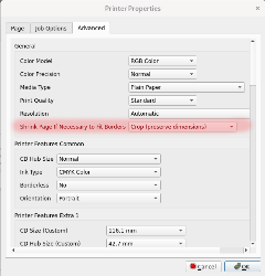
I had the same problem and I solved it with the configuration below.

|
| Free forum by Nabble | Edit this page |


