How to Create a Block
|
I need to create blocks, just like the drawing blocks in autocad. How do I do it? What is the procedure?
Thank you. Sincerely, Del Ventruella |
|
The instructions refere to a "block" command, but I don't see it.
|
|
There appear to be two ways of creating a block, but neither is intuitive.
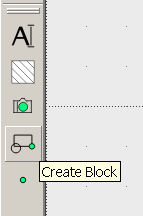
1. There is a Block item in the top menu line, and when I select "create block" I am allowed to select each item separately of the nineteen than I have drawn, select a reference point, and when I press "Enter" I am prompted to enter a name. When I select "save block" I am told that no block has been activated to save, but all the nineteen entities are indicated as selected, but not their associated text. 2. There is a set of block icons in the menu bar that lies along the left side of the screen, within which I can activate the Select window and then define my block by sweeping the cursor with the mouse from upper left to lower right, whereupon every one of the nineteen entities that I have drawn, along with their text elements, show that they have been selected ... but I have progressed no further with that approach. Which one will produce my intended block ? Once that is done and I have successfully saved the block, my plan is to copy it and paste it into my drawing after rotating the entire block by 180 degrees. |
|
Progress:
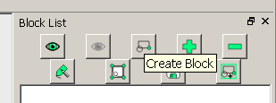
There is a list of blocks for each drawing, which one can find by activating the Layer list and Block list from the View menu list in the top toolbar. The defaults blocks are outlines of a standard drawing with the usual legend where one would list all the scales, changes, etc. Only new blocks that are created in the associated drawing are shown with that drawing. Therefore, after you have selected part(s) of your drawing, not only must you create the block so that you are given the opportunity to name it, but you must also save the associated drawing, or that block will disappear forever. I created a block from my nineteen entities with the protocol that appears under the Block menu item in the upper toolbar, selecting each of the nineteen items by clicking on each one and then pressing Enter, after which I was prompted to select a reference point, followed by another Enter, followed by the prompt to choose a name. That new block then appeared in the block list, only when I then saved the drawing, closed it, and then reopened it. There's more ! I was able to open the saved block for editing in a new window, choose Rotate from the top tool bar under Modify, then choose Select All from the Select menu on the top tool bar. It then prompted me for a rotation point, which I selected, followed by another prompt to choose a reference point, again selected by clicking on a spot, after which moving the cursor caused my block to rotate wildly ... I either hit the mouse button again or pressed Enter (I forget which) followed by a dialog window which thankfully let me select the exact angle (180) as well as deciding whether to keep or delete the original (block). Than I saved it under a new name and saved the associated main drawing. Now I find that I cannot usefully import that block into my main drawing because the block moves wildly about as I move the cursor, and once I have pinned it in anywhere remotely near my original drawing in the open window, going through the move command protocol does not move the block in any controllable way, although I could move the individual entities in my main drawing acceptably reliably. |
|
Tiny step:
I have a couple of blocks, apparently identical, created as above and saved as blocks in the Block list. They consist of the nineteen entities from my main drawing, rotated as a unit by 180 degrees, and then saved with a new name. Now I open the original drawing, select one of my named blocks, and choose Insert Block from the Block menu in the upper toolbar. When I bring the cursor over my main drawing, the block can be seen in outline form, but it cannot be put down in any precise place because there is no "slow" panning setting that I know about, and the Move protocol is similarly flawed. This may be due to an unknown error on my part in setting the original scale of my drawing. I had drawn the outline of the original 12 by 12 inch square plate first and specified its starting point as 0,0 and its upper right hand corner as 12,12 and the units as inches, but when I open the block containing the standard drawing legend and try to import my main drawing, it shows as a tiny square. I will have to figure out how to correct the scale of my drawing so that it fits on the page outline, which I have set under the Preferences dialog. Alternatively, when I save that block as a Block.dxf file, open my original drawing, and then try to import that Block.dxf file, I find that it has reverted to a copy of my original main drawing, not rotated and including the associated text labels of my nineteen entities, which are absent from the actual block in my block list. The changes that I made to the block after creating it (i.e., rotating it by 180 degrees) were not saved when I subsequently saved the block. |
|
Yet another method:
Under the Modify menu item in the upper toolbar there is a Move and Rotate item. I chose that, whereupon I was prompted to select, which I accomplished by clicking in sequence on each of my nineteen entities and then hitting the Enter button, whereupon my drawing started to spin. I was saved by a popup menu which gave me the opportunity to select the rotation angle (180), but I am stymied by an inability to specify a good reference point, and worse, no useful rotation axis, so my rotated group of nineteen entities overlaps the original group, and I cannot move it from there. The good news is that there is indeed a displacement between the two groups. |
|
The problem I'm experiencing above might be circumvented if I can set the point about which my selected block of nineteen entities is to be rotated (and thereby moved). How can I set this rotation point with the command line ? I can easily find the appropriate position of that point by moving the cursor and reading the pair of numbers at the lower left of my 'puter screen. But I can find no command to that effect.
Aha ! Figgered it out. Start from your freshly opened original drawing. Enter the command "ro" which is short for rotate. You will be asked to perform a selection step. What worked for me is the "Select Window" option from among the left-side toolbar icons; after I moved the cursor across my nineteen entities to select all of them, including the associated text labels, I pressed Enter and was prompted for a rotation center (which I previously had measured with the cursor) and entered in the command line window at the bottom of the screen; next is the reference point, which I made the same as the rotation axis. When I subsequently hit Enter again, moving the cursor and hitting Enter yet again opened a dialog box where the exact angle could be set while choosing to delete or retain the original. I chose retain, of course, and that left me with the desired result. |
|
There's still a problem with moving an entity, as the movement of a single selected entity has become impossibly jerky, now that my drawing as twice as many entities in it. I will start a new thread.
|
|
The problem with erratically jumping of to be moved or rotated entities may be due to 'free snap' not activated, so the snapping point will jump to the next possible position. With 'free snap' calm movement becomes possible. You may also switch off snaps you don't want to use, like 'grid'.
You can easily set an exact rotation point at the command line when it says 'specify rotation center' by entering the coordinates (x,y) or relative coordinates (@x,y). Alternatively you may also draw an auxiliary line having start or endpoint as the rotation center and use the mouse to snap to that. There are some manuals at the wiki, though partly outdated they can help about the general working of LibreCAD. Concerning blocks (and also hatchings) there are many known deficiencies. But you have to take LibreCAD as it is, as there are hardly any developers working on it and no one to aim criticism at. |
|
Hello delius - I read through your posting history and had already decided that if I had any direct questions about LibreCad, I would ask you first. Your suggestion to check Free Snap worked wonders for me, although it gives no visual feedback regarding its selection or not selection. I'm sure it wasn't programmed that way; I just haven't become aware of how it tells me, except with the ensuing behavior, which is night & day different and satisfactory.
Now I have progressed to separate files,one with my unadorned entities, the other with their text identifications alone, but suitably arranged still to identify the entities on the finished product, as I intend to have the identities first burned into the raw material (a 12 by 12 inch sheet of 1/8th inch brass) from one file; and then to cut the entities themselves free in a second burn. The text data isn't in the text layer, as it started out in the 0 layer, but I was able to select the drawn entities from the original hybrid 0 layer and delete them, followed by saving that drawing as the text data. I then opened the hybrid 0 layer again (from a separately saved copy), deleted all the text data and saved that file as the entities-only file, thereby leaving me with two separate files for the separate laser-cutting operations. This saved me from the Create Block hassle which I have yet to solve. Best regards, georgesbasement |
|
In reply to this post by georgesbasement
Okay, But employer sprang for AutoCAD, so I won’t be using this software anymore. Del Ventruella | Senior Engineer
| High Voltage Maintenance Corporation | Wright--Patterson AFB WPAFB | Area B | 2424 E Street| Bldg. 62 | High Voltage Maintenance | WPAFB, Ohio 45433 T 937 823 9782 | F 937 252 3293 From: georgesbasement [via LibreCAD] [mailto:ml+[hidden email]]
Progress: If you reply to this email, your message will be added to the discussion below: http://forum.librecad.org/How-to-Create-a-Block-tp5715012p5715151.html
To unsubscribe from How to Create a Block,
click here. |
|
Just to help others - in my copy of LibreCAD 2.1.3, compiled on 23 september 2016, Layers and Blocks are NOT listed under "View" on the top line. The only way I can find of opening them, non-intuitively, is from the top line/Widgets/Dock Widgets.
|
| Free forum by Nabble | Edit this page |


