How to plot a survey plan using "Surveyor's Units" in LibreCAD

Previous Topic Next Topic
 
classic Classic list List threaded Threaded
12 messages Options
Reply | Threaded
Open this post in threaded view
|

How to plot a survey plan using "Surveyor's Units" in LibreCAD

IntellectArchitects
Greetings!

Am trying to plot out a survey plan with libreCAD but am getting errors in my commands.

Using AutoCAD and on Dynamic input one can easily use similar command like @72.30<N82d15'E  to achieve a line which differs from just typing  @72<82 .

But when I type such command as  @72.30<N82d15'E  libreCAD says it's an error command.

Someone should please help.

Is there a way to on dynamic input on libreCAD?,
Is there a different way to issue such command in libreCAD?

Please note: i have on <b>Surveyor's Units  as my angle unit from preferences yet it didn't work

Help please somebody!

Reply | Threaded
Open this post in threaded view
|

Re: How to plot a survey plan using "Surveyor's Units" in LibreCAD

Gary S
LibreCAD doesn't support a compass bearing as an input.  The bearing needs to be converted to an angle.  'Surveyor's Units' in the preferences is for output on the status bar or for dimensioning.

"@72.30<82.25" would work on the input line and would appear on the statusbar as "72.30<N82d15'E"
Reply | Threaded
Open this post in threaded view
|

Re: How to plot a survey plan using "Surveyor's Units" in LibreCAD

IntellectArchitects
Thanks so much for your reply Gary S. 

But LibreCAD still writes "Expression syntax error". Any idea on how to still go about that Sir?

 See below image:

Command output


Reply | Threaded
Open this post in threaded view
|

Re: How to plot a survey plan using "Surveyor's Units" in LibreCAD

dellus
No feet (') or inches (") symbol in the angle value. In Gary's answer it's meant as quotation mark.
Reply | Threaded
Open this post in threaded view
|

Re: How to plot a survey plan using "Surveyor's Units" in LibreCAD

IntellectArchitects
Survey plan


dellus, thanks!

But i tried it out and it give me seperate thing from what i expected and i went further to study the conversion of bearing to decimal and it seems to go inline with you guys instructions.

But, the issue i have is that it still not conform to what is on the  surveyor's plan so i decided to attach the image of the plan here.

Please kindly check it out and let me know where i missed it, you can as well try it out.

* maybe i did it wrongly?
* or is the error from the surveyor?

See image above.
Reply | Threaded
Open this post in threaded view
|

Re: How to plot a survey plan using "Surveyor's Units" in LibreCAD

Gary S
As I recall (it's been a while since I did this), but bearings are measured clockwise with 0 degrees at the 12 o'clock position while LibreCAD measures angles counter/anti-clockwise with 0 degrees at the 3 o'clock position.  The conversion from bearings to degrees required a couple of steps.  I once had a spreadsheet to do the conversion, but it seems to have disappeared into the ether.  If I do find it, I'll post it here.


EDIT: Found it:SitePlanCalculations.ods
Reply | Threaded
Open this post in threaded view
|

Re: How to plot a survey plan using "Surveyor's Units" in LibreCAD

IntellectArchitects
       

Gary S, i really appreciate this, thank you so, so much. This will certainly work .

Big thanks to you also, dellus. Your effort was really appreciated.

 hope we meet again!
Reply | Threaded
Open this post in threaded view
|

Re: How to plot a survey plan using "Surveyor's Units" in LibreCAD

Gary S
You are welcome.  BTW, use the value in Column G for the angle when drawing the line..
Reply | Threaded
Open this post in threaded view
|

Re: How to plot a survey plan using "Surveyor's Units" in LibreCAD

dellus
In reply to this post by IntellectArchitects
Ha, now Gary has been quicker.

' and " of course are minutes and seconds.

I have done a run and found this method:

I started at point T 5031 CN.

The input would have to be (startpoint 0,0) for second point @40.60<90-324-28/60

90 is for correction of north as 0°, the minuses for opposite angle direction, x/60 for the minutes.

In the end of the last line we do not meet 0,0 exactly. A little bit off.

intellitect.dxf
Reply | Threaded
Open this post in threaded view
|

Re: How to plot a survey plan using "Surveyor's Units" in LibreCAD

LordOfBikes
Administrator
A bit more general conversion solution:
https://forum.librecad.org/Coordinate-system-conflict-tp5720965p5720976.html
I missed the minutes aspect, but in combination with dellus' solution, this should be no problem.
investing less than half an hour into Search function can save hours or days of waiting for a solution
Reply | Threaded
Open this post in threaded view
|

Re: How to plot a survey plan using "Surveyor's Units" in LibreCAD

obix
In reply to this post by Gary S
Gary S wrote
I once had a spreadsheet to do the conversion, but it seems to have disappeared into the ether.  If I do find it, I'll post it here.

EDIT: Found it:  SitePlanCalculations.ods
I found the .ods file Gary_S shared very helpful in getting on the right track with this issue, thanks Gary_S!  So I wanted to share what I progressed in this converter spreadsheet.  The original sheet is still included.

To use the worksheet:
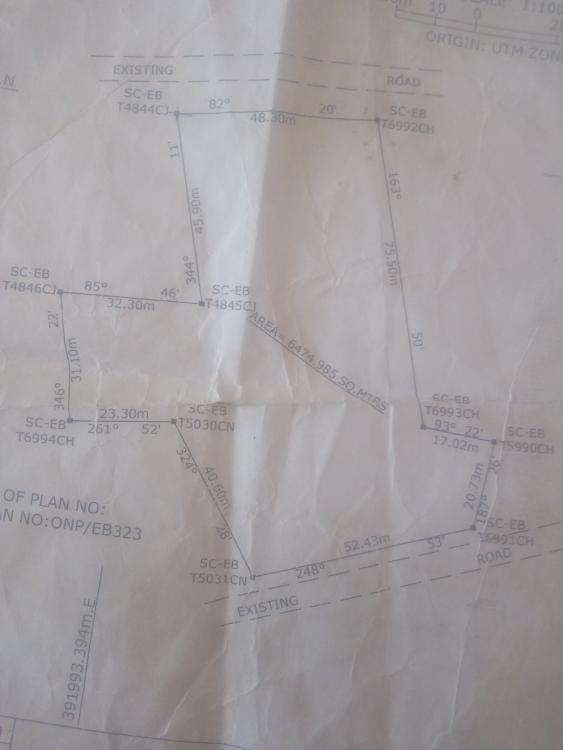
  1) Enter all the distances and bearings in the 'Survey Loop' table
  2) Copy the 'Command' column from the adjacent 'LibreCAD' table
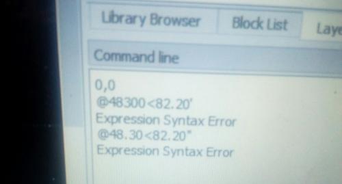
  3) In LibreCAD, select the '2 Point Line' or enter 'line' in command box
  4) Set the starting point, I typically use 0,0
  5) In LibreCAD versions 2.2 and newer, click the menu button next to command box and select 'Paste Multiple Commands', this should enter everything from the worksheet

Hope someone finds this helpful!

SurveyLoopToLibreCAD.ods

If you think you can, or you think you can't, you're probably right.
Reply | Threaded
Open this post in threaded view
|

Re: How to plot a survey plan using "Surveyor's Units" in LibreCAD

Jaycad
Bearings.ods

Here's one I prepared earlier.  It probably doesn't add anything to what has already been posted but I'll post it anyway.  The Mils to Librecad sheet converts bearings in mils to LibreCad angles - I wrote it to transfer bearings from a military compass to LibreCad.  It has a handy DMS-decimal degrees conversion.

The other sheet converts theodolite angles and a distance to relative coords from a station.