Welcome Jscoyne2!
Line endings aren't important in CAD, so LibreCAD has no setting for this.
Also line thickness in CAD is ruled by national and international standards and are mainly used to distinguish different drawing elements.
For any kind of machining you usually use CAD to make a drawing in finished measure.
Then use this drawing with a CAM tool, usually called post processor.
The task of the post processor is to take the drawing and create a program for machining.
This requires to create tool paths which compensate the diameter of the tool (e.g. laser, mill or water jet) and possibly other strategies to apply, e.g. not to hurt the boundaries or moving between paths.
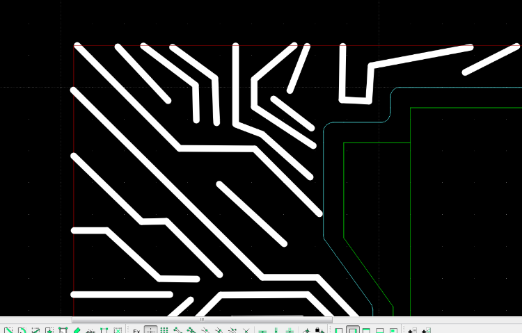
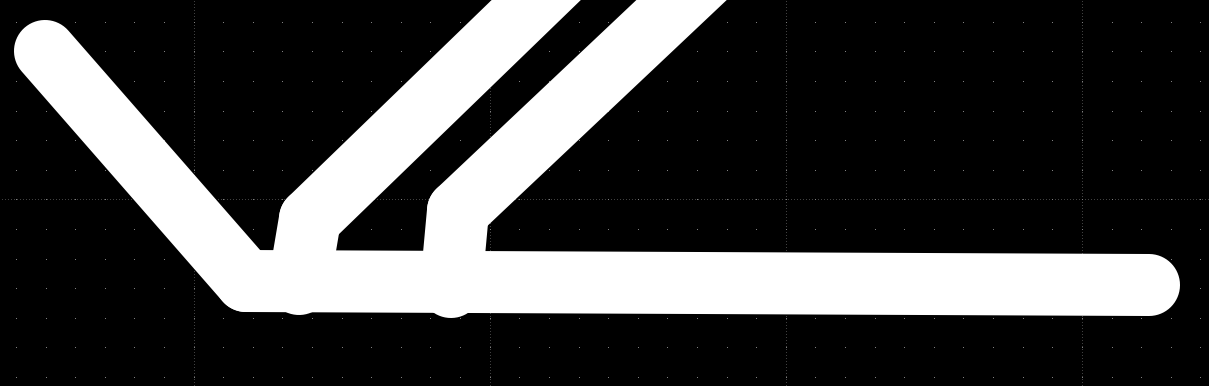
So when you need the outline of the 2.1mm line, you can search if there is any other software out there which can do this better or out of the box.
Inkscape has some machining capabilities with plugins, but I can't say if there is one that fulfill your needs.
What you try to achieve is common in PCB manufacturing. There are CAM tools which can create CNC programs to move on the outline of wires to isolate them.
Nor have I used one, nor can I recommend one, but I know they are used out there.
Finally, if nothing helps, you can draw the outlines yourself.
I would start with the lines you have on a separate layer and default width.
Make a parallel boundary box with 1.05mm distance, this is where the lines should end, that the outlines don't hurt the real boundary.
Then on a new layer I'd create the outlines with parallel and tangent tools.
Sounds like a whole bunch of work, so searching for a software that fulfill your needs may be the better solution.
If you already have a manufacturer for laser cutting, maybe he can recommend which tools to use or which kind of drawing is required.
If this is your own laser cutter, there may be a community of other users who can help better with this.
investing less than half an hour into Search function can save hours or days of waiting for a solution