Polar copy
|
Hi,
I would like to draw a 360° protractor, with an index every 10 degres, and a text ("10°"; "20°"; "30°"... "350°) near the index. I wonder if there is something like "multiple polar copy" where an entity is selected ( i.e a line or a text) and copied n times with a rotation amoungst center between each copy. I tried Tools/modify/move and rotate but this do not result to the expected behaviour as we only can define de "final-point", not the center of rotation. What I would like to do: I draw a line from point (0,100) to (0,110) : a 10 Units long line on the Y axis, Copy this line 36 times with central point of rotation = (0,0) and an angular distance of 10 degres between each copy. A simpler way to describe waht I try to reach is haow to draw a clock with a dot (or line) every 5 minutes and a text showing the hour ( 1...12) Is there a (simple) way to achieve this with LibreCAD ? Thanks best regards JMJ |
|
Administrator
|
Hi,
use Roate, not Move and Rotate! This will do exactly what you've described. Draw one line and one text, select both and use Tools/Modify/Rotate. Follow the hints near the command line and status bar and then, in the Rotate dialog select multiple copies. Enter 35 copies, change the angle to 10° if it is not exact, that's it. Then use Tools/Modify/Properties to change the texts. Armin
investing less than half an hour into Search function can save hours or days of waiting for a solution
|
|
Hi,
Thanks a lot, I got it ! ... Exept that I cannot edit the text with "Tools/Modify/Properties" => I have not found where something editable comes up ( no editable field nor pop-up, nor...) best regards JMJ |
|
Administrator
|
This should appear, just with a single left click on the text:
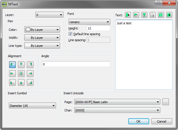 The mouse pointer is a cross when the Properties tool is active.
investing less than half an hour into Search function can save hours or days of waiting for a solution
|
|
Hi,
Thanks again. I am Running LibreCAD 2.1.3 on W10. When I left click on the text ( wich is "toto" in this example) : 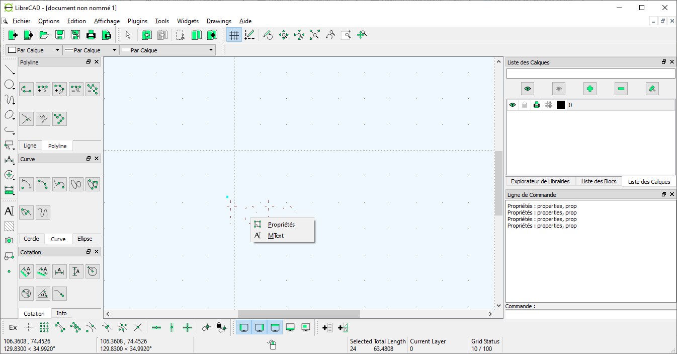 Would you suggest are-installation ? Best regards JMJ |
|
Ok, Got it,
1) select text to be able to select "properties" by left click 2) select text to edit the double selection is very contra-intuitive for me anyway, thanks jmj |
|
Administrator
|
Sorry, I haven't used 2.1.3 for a while now and were not aware of this difference.
In 2.2.0 a simple left click is enough. You can use latest 2.2.0-rc4... release candidate, which is safe to use from here: https://github.com/LibreCAD/LibreCAD/releases/tag/latest Or wait a couple days, the final release of official 2.2.0 is coming soon. Armin
investing less than half an hour into Search function can save hours or days of waiting for a solution
|
|
In reply to this post by jmj
I am an 62 years old Engineer ( Mechanical + Electronical).
I started to "draw" almost 40 years ago, with pencils and china-ink, and then with several softwares. I belong to a astronomical club, for wich I realised an Armillary sphere -- for educational purposes -- on my CNR router. I use CamBam to draw what then will then translated in G-Code to pilot the CNC-Router. There is no possibility to draw any dimension on such tool as the G-Code "includes" the each and every dimensions. For instance, this is how the "cercle de declinaison" is drawed with CamBam : 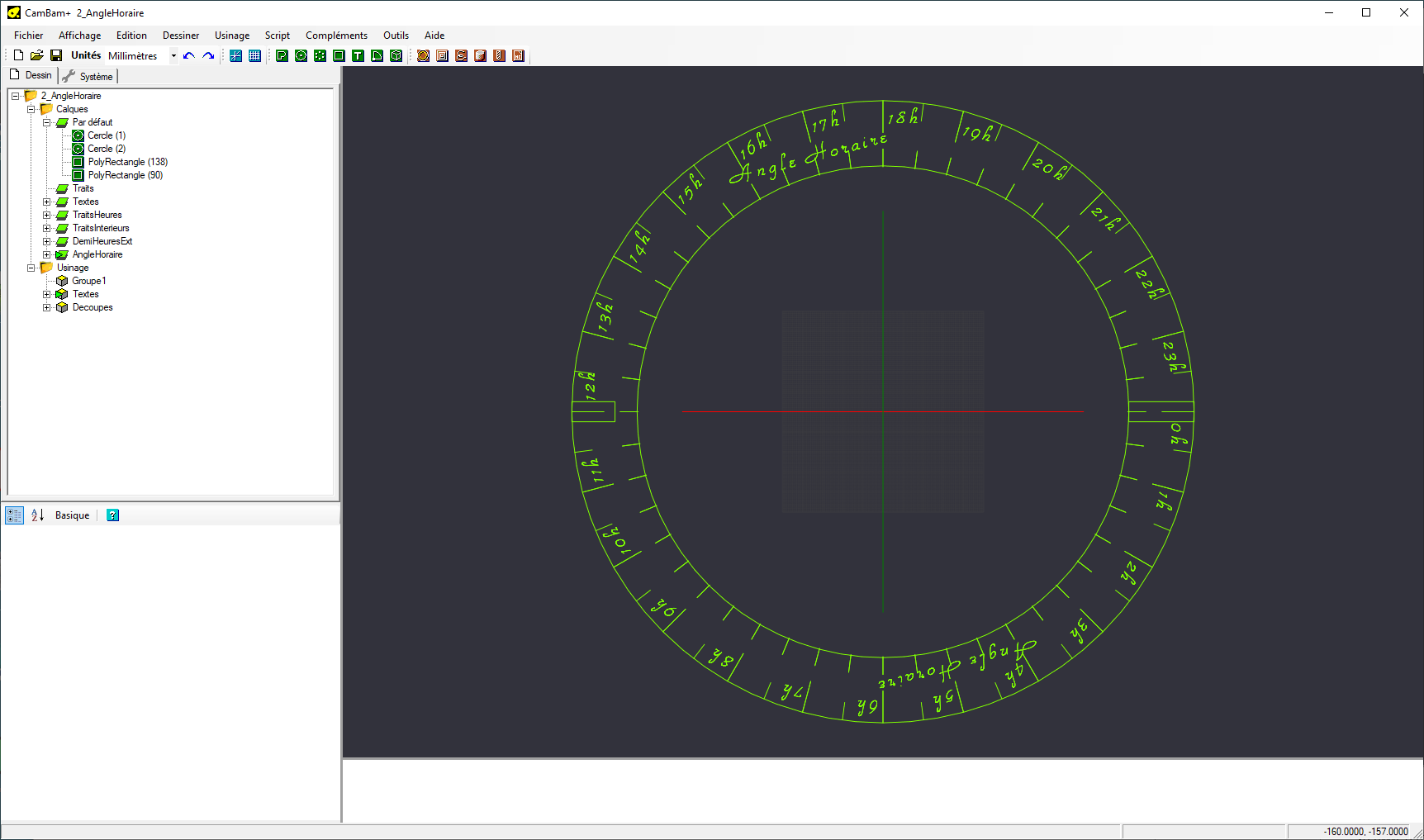
and this the result : |
|
-- only on image per post so I continue here --
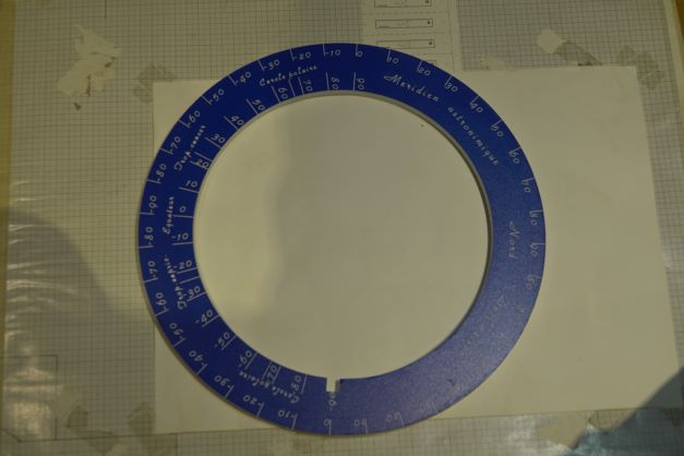 . .
I would like to communicate to others astronomical clubs the draing -- with dimensions -- of this realisation, and try to redraw everythig with LibreCad as it is mentionned in the top 5 2D-CAD Tools. After a "VERY" long learning time -- nothing is intuitive, not even cut and paste between layers I managed to reach this: |
 Obviously the two "90" indexes are not aligned as the two "0" indexes. (external circle diam. = 333mm, internal circle diam. is 245mm) Is there a way to correct this ? = I guess that the selection of the "rotation center" is not exacltly 0 -- by mouse pointing-- ,is there a possibility to enter the coordinates of this point in a text field ( command ) ? best regards JMJ |
|
Sorry I posted the wrong CamBam screen copy ( does not match the "realised" picture )
here it is... 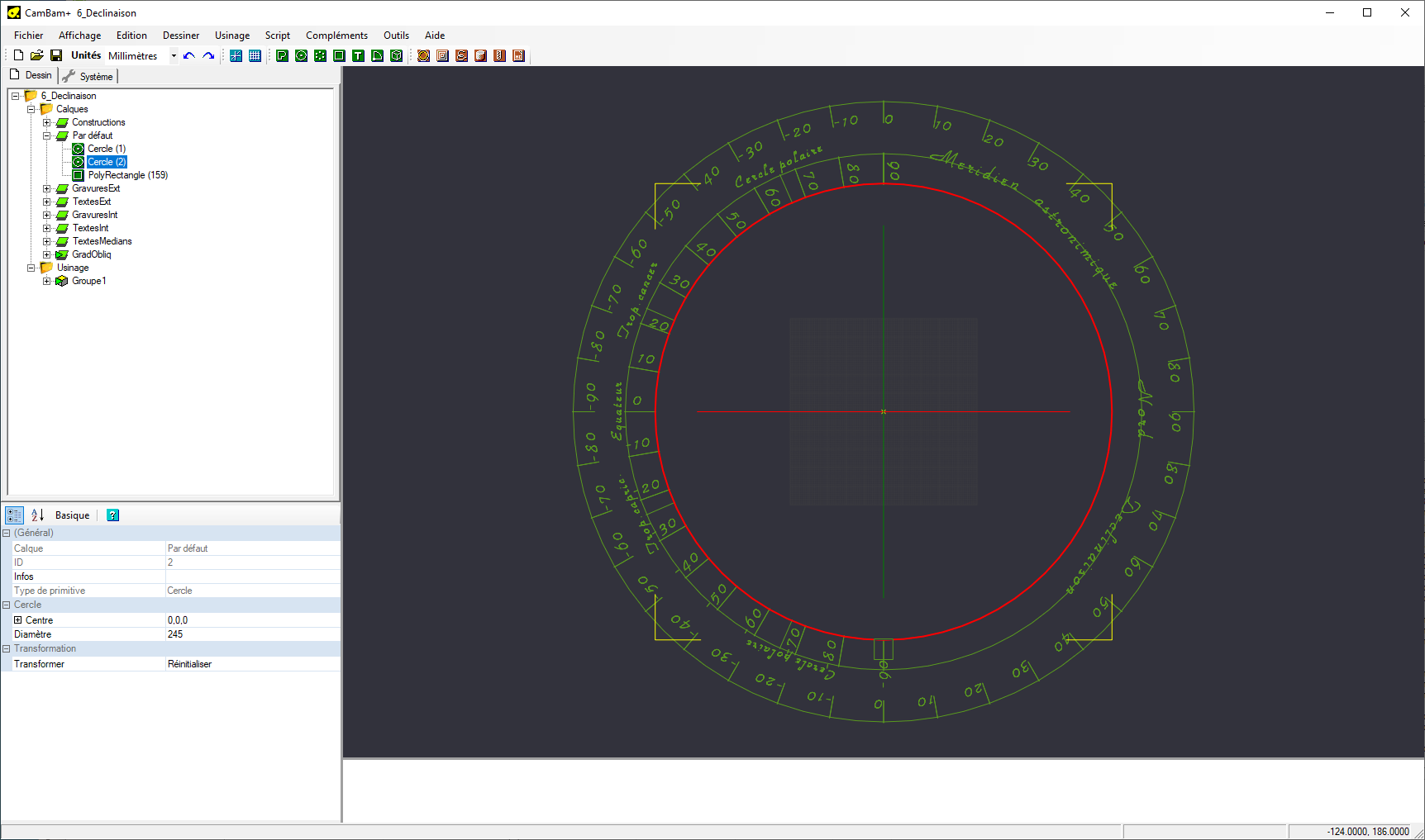 |
|
Of course.
At the command line activate the "Command:" field by clicking into it, then type 0,0 and press "Enter". |
|
Administrator
|
In reply to this post by jmj
Basically, you can always enter coordinates in the command line, when a mouse click is expected.
See https://librecad.readthedocs.io/en/latest/guides/cmdline.html for more information. From your screenshot I see that you have no snaps activated. Find them in bottom left corner above the coordinates. It is recommend to always activate Free Snap, 2nd from left and combine others by need. To snap on the origin at 0,0 you can use Snap on grid. See https://librecad.readthedocs.io/en/latest/ref/snaps.html Concerning the misalignment I assume that this is caused by negative numbers and different number widths. When the text anchor is in the center, different text width can be the reason for deviating distances between the text and the tick marks. Maybe placing the text center aligned under its mark can solve this issue. Selecting a text shows a little green dot, which represents the text anchor. Changing the anchor is done in the Properties dialog (Alignment). With left mouse button pressed over the text, move the mouse and you can drag the text to relocate it.
investing less than half an hour into Search function can save hours or days of waiting for a solution
|
|
Hi,
I finally managed to do draw everything I wanted. Great tool ! Many thanks for the realized work. Very, very impressive . As I only "draw" a very few time in the year, let's say once every 2 monthes (enough time between 2 utilisation, to forget how you did it the last time), I will write for myself, in french, something I could call "Tips and Tricks" wich will summarise all the for-me-contra-intuitive behaviours of the tool as well as all the required steps to draw this : 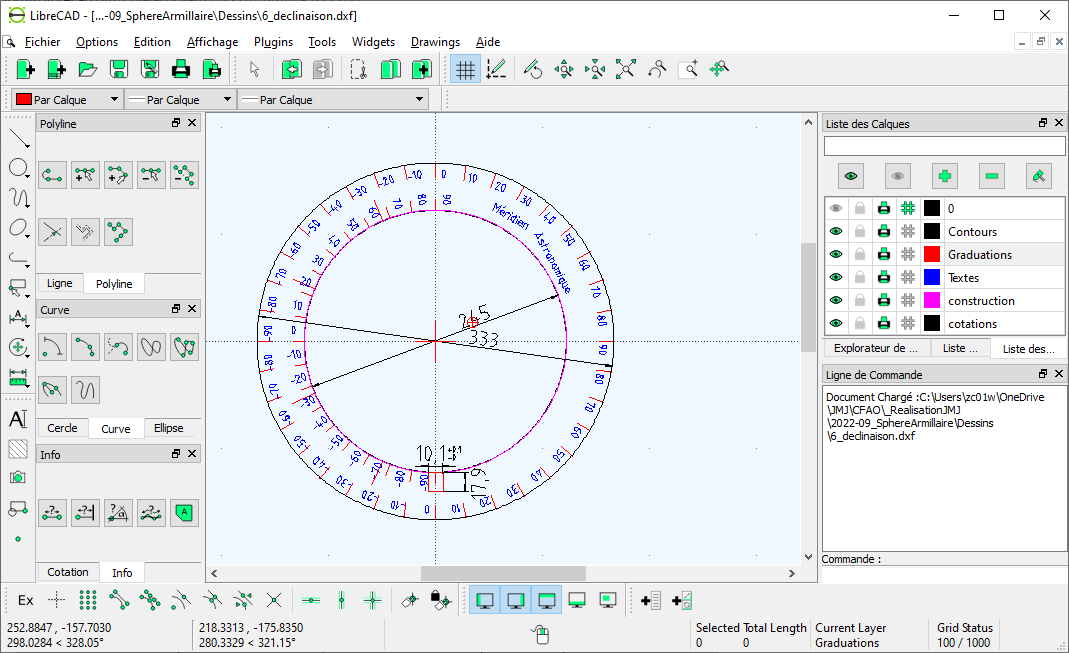 I will follow my own rules for writing documentations/manuals. (Latex => PDF, not HTML or other formats) I am ready to give this documentation, if you are interrested. Could be my contribution to the project if you give me some time (a couple of monthes) to achieve it. Again many thanks, great product and incredible support. Best regards and seasons' greetings JMJ P.S : a last question appears as I prewiew my post : The way the text "Meridien Astronomique" is drwaned is not satisfacory : is there a way to "write along a path" (so that this text could be writen along an "Arc" defined as "Path for text"? |
|
Unfortunately there is no text along path tool in LibreCAD.
For a work - around you could use the same technique as with angles text, rotating a single letter and then editing each single rotated one. I think a font where all letters take the same space might be best. Quite tedious.... Have fun experimenting! |
«
Return to CAD
|
1 view|%1 views
| Free forum by Nabble | Edit this page |

