I made a new file to illustrate it and test with.
1) 6 different layers, each with a different line width set on the layer.
2) 1 manual layer - basically just has the default 0.00 width set on the layer.
I then made a simple shape and some text to show progressively getting thicker line widths.
The first row is all manual - it's to estimate how to make the PDF line thicknesses look similar to the thinner line widths on screen
- and just to make sure that my verbiage is clear...
- Looks Good on Screen - Corresponding manual set to look good in PDF
- .09mm - .18mm
- .13mm - .30mm
- .18mm - .40mm
- .25mm - .80mm
- .50mm - 1.40mm
- .70mm - 2.00mm
- OBVIOUSLY when you set something to 2.00mm it looks rediculous on screen print-preview... but when you print it, the 2.00mm looks like what you'd expect from the .70mm....
Then I did columns for each layer-set thickness. A column for the 0.09 mm, a column for 0.13mmISO, etc. up to 0.70mmISO. My goal was to test if it mattered if you set the line thickness by layer or manually...
The last column is for the manual-set thickness layer. Each line going down is set to the thickness shown next to the shape. I did this to make sure that if the layer is set to 0 explicitly, does that change anything?
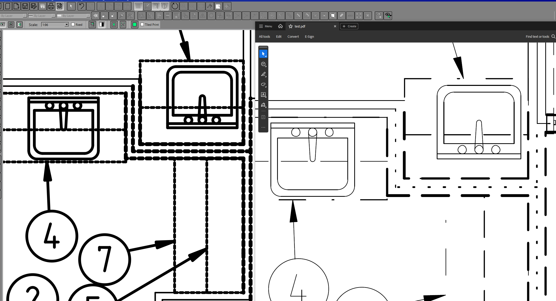
The dxf is listed below, as is the test.pdf (printing to Microsoft Print to PDF) and the test_export.pdf (exported to PDF). I also tried exporting to PNG but couldn't get that to work at all.
testing.dxftest.pdftest_export.pdf(*edit* - formatting to make it readable)