Dimension styles


|
This may actually summarize several things posted in part elsewhere.
I've figured out that to use dimensions, I try overall scale first, then tweak individual parts. This seems to work for me. But it appears that the "styles" may be very limited (or I'm not understanding...). I would like to use dimensions of the style: /-------- 14' - 2" --------/ where the dimension is placed in a gap in the line and, a bit less important (unless you are doing architectural), using the "fat slash" type tick at the endpoints instead of an arrow. Is LibreCAD able to be configured to do this style dimensioning? or is the style: 14' - 2" <------------------------> The only available style? |
|
|
I can kind of help with the first question. Select "Options" -> "Current Drawing Preferences". On the left hand side of the dialog box set the "Text alignment" to "Horizontal". It will place the dimension text within the line, but it will read along the X-axis, even for vertical lines.
For the second question: Again on the "Current Drawing Preferences", on the right hand side under "Dimension lines, arrows & ticks" set the "Arrow size" to "0" (type "0" as it is not in the drop-down) and select the "Tick size" from the drop-down or provide another value as necessary. |
|
|
In reply to this post by jep1955
You can place the cyphers in the middle of the dimension line with "dimension line gap" (meaning distance text to dimension line) = minus text height / 2, but the dimension line will not be cut out in aligned mode. As it works in horizontal mode, it seems not so difficult to code, but sadly it's not done.
Concerning the tick, you don't necessarily have to set the arrows to 0, if you give the tick a value more than 0 this overrides the arrow anyway. |
|
|
Thanks for all the help so far. I have indeed set an appropriate tick size and zero arrow size. And doing the offset for text – “minus height / 2” positions it correctly. So – It is very close to what I am trying to accomplish. The dimension line still goes through the text. It doesn’t “break” or give a gap for the text no matter what settings I try. And I have tried both horizontal and aligned. Wish there was a better selection of fonts. I would prefer an older style “hand drawn” font and the ability to bold it or something (same goes for normal text). In dimensioning, overriding the width options from “by layer” to a value – even a very large value for text, dimension lines, or ticks seems to have no effect. But changing the tick size does indeed change the length. I started with a general scales of 10 and then modified the individual values. Any more typical settings than the default which leaves text and arrows and so on so small you can’t see that they exist? Thanks again for the very helpful hints. Sent from Mail for Windows 10 From: dellus [via LibreCAD] <ml+[hidden email]>
Sent: Tuesday, December 19, 2017 3:59:58 PM To: jep1955 Subject: Re: Dimension styles You can place the cyphers in the middle of the dimension line with "dimension line gap" (meaning distance text to dimension line) = minus text height / 2, but the dimension line will not be cut out in aligned mode. As it works in horizontal mode, it seems
not so difficult to code, but sadly it's not done.
Concerning the tick, you don't necessarily have to set the arrows to 0, if you give the tick a value more than 0 this overrides the arrow anyway. If you reply to this email, your message will be added to the discussion below:
http://forum.librecad.org/Dimension-styles-tp5715598p5715601.html
|
|
|
Line thickness is shown right on screen in drawing mode only at a scale of 1:1.
As you do architectural drawings you will have a much smaller scale, and you can see the proper look only in the print preview mode. It is best to make yourself a template with the dimensioning settings you like, and then use it for future new drawings and adjust to a different scale with "General Scale". You don't have to change the other values any more. Except for "Fixed Length" extension lines if you use that, these sadly do not respond to "General Scale". Is there a good reason for that? Some time ago I have tried to make a template for architecture in inches as unit. I have no knowledge about standard architectural scales in the imperial world (US), so i choose 1:96 as it's closest to metric standard 1:100. Probably wrong. I include it here so you may have a look at it. Maybe you could make a template for other American fellows, there often are questions on that in the forum. arch_inch_1_96_letter.dxf Concerning fonts, in the main LibreCAD program folder there is a ttf2lff.exe. With this you can turn a windows ttf font to a LC lff font. But it only makes an outline. If you take a quite "sticky" font it might look acceptable. I have tried it out prior to writing this and got an error "freetype6.dll not found", but I remember to have had it working some time ago. You may play with this. |
|
|
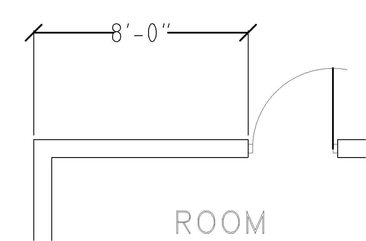
Finally getting around to responding. Architectural drawings (ANSI) are typically either C, D or E size. (18x24, 24x36, and 36x48 for architectural – engineering is slightly smaller based on multiples of 8.5x11). Typical scales would be 1/8” = 1’ or 1/4” = 1’ (1:96 and 1:48). Depends a bit on the size of the job. A lot of residential is on C while small commercial is often D and large commercial would be E. Setting overall dimension scale to 1 and setting the other values worked much better. In drawing mode or print preview, there are still a few things that could be nicer, but I can live with this. No matter how I set scales for Arrow/Tick Line Thickness, the ticks are still skinny. I can’t get fatter ticks. But I can live with that. The gap for the dimension text is almost correct, but should be a bit wider as it actually touches the number on the left side and looks correct on the right side only because the “ for inches is above the center so the line doesn’t touch it. Is there a way to send screenshots here? There are a couple of fonts I may experiment with. As long as open source, if they work, I will supply them. All I need is an architectural set of fixtures! Oh – if I modify the block that is in the block list, will all blocks update by any chance? Sent from Mail for Windows 10 From: dellus [via LibreCAD] <ml+[hidden email]>
Sent: Wednesday, December 20, 2017 4:33:48 PM To: jep1955 Subject: RE: Dimension styles Line thickness is shown right on screen in drawing mode only at a scale of 1:1.
As you do architectural drawings you will have a much smaller scale, and you can see the proper look only in the print preview mode. It is best to make yourself a template with the dimensioning settings you like, and then use it for future new drawings and adjust to a different scale with "General Scale". You don't have to change the other values any more. Except for "Fixed Length" extension lines if you use that, these sadly do not respond to "General Scale". Is there a good reason for that? Some time ago I have tried to make a template for architecture in inches as unit. I have no knowledge about standard architectural scales in the imperial world (US), so i choose 1:96 as it's closest to metric standard 1:100. Probably wrong. I include it here so you may have a look at it. Maybe you could make a template for other American fellows, there often are questions on that in the forum. arch_inch_1_96_letter.dxf Concerning fonts, in the main LibreCAD program folder there is a ttf2lff.exe. With this you can turn a windows ttf font to a LC lff font. But it only makes an outline. If you take a quite "sticky" font it might look acceptable. I have tried it out prior to writing this and got an error "freetype6.dll not found", but I remember to have had it working some time ago. You may play with this. If you reply to this email, your message will be added to the discussion below:
http://forum.librecad.org/Dimension-styles-tp5715598p5715606.html
|
|
|
So 1:96 was o.k. I just used letter size because anyone with an ordinary consumer model printer can test if the print outcome is right.
"Setting overall dimension scale to 1 and setting the other values worked much better." Can you explain more? I just would like to find out what is a standard AutoCAD - conform procedure, if there is any, for not to make wrong recommendations and templates. Arrow/Tick Line Thickness works for me. Arrow/Tick and dimension line thickness can only be set together, not separately. The extension lines thickness can be set separately. The width of the cyphers is a matter of the general line properties of the dimensioning. 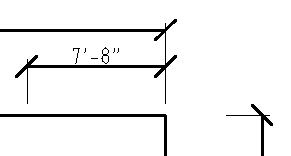 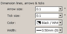 You can upload a screenshot with "Insert Image"  Fixtures: in the Forum under "CAD templates, blocks etc...." in "Blocks" by claus82 he offers the library "arch_blocks.zip". Probably metric though. "Oh – if I modify the block that is in the block list, will all blocks update by any chance?" I'm not an expert with blocks, but I made a quick test and when I modified the block in the separate window the copies in the original drawing changed instantly. Or have I misunderstood you? |
|
|
There seem to be some general peculiarities occasionally. I even had a lockup and crash. But they are not common. Sometimes I have to save, restart LibreCAD and then suddenly things work. Arrow Tick indeed work as you mention. Common HANDDRAWN practice is that the tick would be thick, but the line not. I will fire up AutoCAD and see what it does (now – compared to what it did years ago! 😊) The “gap” not being wide enough is a bit annoying. But I will try other fonts and see if this is a general problem or specific font related. If I import the downloaded blocks and import, I end up with a layer called Contours and if I try to move the object/block to the correct layer, very bad things happen (including the earlier mentioned crash). Similar problems and hangs happen every time I try to load the blocks. I have not tried re-importing one of my saved blocks. I’ll let you know. The fact that all blocks update when updating the master is very good! I DID discover that you do not want to insert a block and later decide that in order to put in more places copy it. You need to do the normal block insert again. If you copy and paste you start getting a large number of duplicate blocks in the block list (Sink, Sink-0, Sink-1, etc). This may be normal even in AutoCAD however. I do a lot from the command prompt (since that is how I originally learned AutoCAD). Every now and then the command window loses focus and as I try to type commands and instead of the command window accepting “circle”, it gets as far as “ci” gives and error, then “rc” and gives an error. It’s something I am doing… A couple of odd things (but you would drive everybody crazy if you change now). In AutoCAD trim, you select the limiting entity and then select the bit to REMOVE. In AutoCAD, (unless they changed it), they use the term “break” instead of “divide”. (Divide might be a better term though). I’m not sure if AutoCAD (LT) feel was the intent or not? I would probably use this differently if I could come up with a useful toolbar arrangement. Right now I have some on the right, some on the bottom, and some on the top. I’m almost done with my drawing and I am going to take it somewhere and print a copy at Architectural C size to see what it looks like. When I get something useful as a real USA ANSI template, I will let you know the settings. Sent from Mail for Windows 10 From: dellus [via LibreCAD] <ml+[hidden email]>
Sent: Friday, December 22, 2017 5:29:24 PM To: jep1955 Subject: RE: Dimension styles So 1:96 was o.k. I just used letter size because anyone with an ordinary consumer model printer can test if the print outcome is right.
"Setting overall dimension scale to 1 and setting the other values worked much better." Can you explain more? I just would like to find out what is a standard AutoCAD - conform procedure, if there is any, for not to make wrong recommendations and templates. Arrow/Tick Line Thickness works for me. Arrow/Tick and dimension line thickness can only be set together, not separately. The extension lines thickness can be set separately. The width of the cyphers is a matter of the general line properties of the dimensioning.   You can upload a screenshot with "Insert Image"  Fixtures: in the Forum under "CAD templates, blocks etc...." in "Blocks" by claus82 he offers the library "arch_blocks.zip". Probably metric though. "Oh – if I modify the block that is in the block list, will all blocks update by any chance?" I'm not an expert with blocks, but I made a quick test and when I modified the block in the separate window the copies in the original drawing changed instantly. Or have I misunderstood you? If you reply to this email, your message will be added to the discussion below:
http://forum.librecad.org/Dimension-styles-tp5715598p5715618.html
|
|
|
In reply to this post by dellus
From: dellus [via LibreCAD] <ml+[hidden email]>
Sent: Friday, December 22, 2017 5:29:24 PM To: jep1955 Subject: RE: Dimension styles So 1:96 was o.k. I just used letter size because anyone with an ordinary consumer model printer can test if the print outcome is right.
"Setting overall dimension scale to 1 and setting the other values worked much better." Can you explain more? I just would like to find out what is a standard AutoCAD - conform procedure, if there is any, for not to make wrong recommendations and templates. Arrow/Tick Line Thickness works for me. Arrow/Tick and dimension line thickness can only be set together, not separately. The extension lines thickness can be set separately. The width of the cyphers is a matter of the general line properties of the dimensioning. You can upload a screenshot with "Insert Image" Fixtures: in the Forum under "CAD templates, blocks etc...." in "Blocks" by claus82 he offers the library "arch_blocks.zip". Probably metric though. "Oh – if I modify the block that is in the block list, will all blocks update by any chance?" I'm not an expert with blocks, but I made a quick test and when I modified the block in the separate window the copies in the original drawing changed instantly. Or have I misunderstood you? If you reply to this email, your message will be added to the discussion below:
http://forum.librecad.org/Dimension-styles-tp5715598p5715618.html
|
|
|
In reply to this post by dellus
About me, by the way… I knew how to read blueprints since I was 5 and my dad (and Engineer) would drag me around the USA and I would hold the end of the tape measure for him. He used to design churches. I got my degree in Electrical Engineering in the 70’s, but ended up in computers, then software and work in the inspection industry. I am the Software Quality Manager for Nikon Metrology (a division of Nikon Camera). So, I tend to look at things with a bit of a critical eye! Not picking on anybody though! I love LibreCAD. My CAD work is typically mechanical design, but I often do reverse engineering of architectural for homes and churches (mostly for fun). John Sent from Mail for Windows 10 From: dellus [via LibreCAD] <ml+[hidden email]>
Sent: Friday, December 22, 2017 5:29:24 PM To: jep1955 Subject: RE: Dimension styles So 1:96 was o.k. I just used letter size because anyone with an ordinary consumer model printer can test if the print outcome is right.
"Setting overall dimension scale to 1 and setting the other values worked much better." Can you explain more? I just would like to find out what is a standard AutoCAD - conform procedure, if there is any, for not to make wrong recommendations and templates. Arrow/Tick Line Thickness works for me. Arrow/Tick and dimension line thickness can only be set together, not separately. The extension lines thickness can be set separately. The width of the cyphers is a matter of the general line properties of the dimensioning. You can upload a screenshot with "Insert Image" Fixtures: in the Forum under "CAD templates, blocks etc...." in "Blocks" by claus82 he offers the library "arch_blocks.zip". Probably metric though. "Oh – if I modify the block that is in the block list, will all blocks update by any chance?" I'm not an expert with blocks, but I made a quick test and when I modified the block in the separate window the copies in the original drawing changed instantly. Or have I misunderstood you? If you reply to this email, your message will be added to the discussion below:
http://forum.librecad.org/Dimension-styles-tp5715598p5715618.html
|
|
|
In reply to this post by dellus
In general, things are going well. I am working on some “standards” for US. Fonts work fine if you set the layer line width for text (or set the attributes) to something large enough to “fill in”. Looks good. I have an architect font (Free) but can’t convert as I get a message about FreeType6.dll missing or something similar? Now, I have to figure out how to create a drawing, scale it, and drop it onto a paper size template (I might want to print with title block on ARCH B or ARCH D depending on need – and I do NOT want the border/block to scale). Hope you had a great Christmas. Oh – I’m so slow sometimes. Cute name. LibreCAD. And I was looking for a “free” CAD package. 😊 John Sent from Mail for Windows 10 From: dellus [via LibreCAD] <ml+[hidden email]>
Sent: Friday, December 22, 2017 5:29:24 PM To: jep1955 Subject: RE: Dimension styles So 1:96 was o.k. I just used letter size because anyone with an ordinary consumer model printer can test if the print outcome is right.
"Setting overall dimension scale to 1 and setting the other values worked much better." Can you explain more? I just would like to find out what is a standard AutoCAD - conform procedure, if there is any, for not to make wrong recommendations and templates. Arrow/Tick Line Thickness works for me. Arrow/Tick and dimension line thickness can only be set together, not separately. The extension lines thickness can be set separately. The width of the cyphers is a matter of the general line properties of the dimensioning. You can upload a screenshot with "Insert Image" Fixtures: in the Forum under "CAD templates, blocks etc...." in "Blocks" by claus82 he offers the library "arch_blocks.zip". Probably metric though. "Oh – if I modify the block that is in the block list, will all blocks update by any chance?" I'm not an expert with blocks, but I made a quick test and when I modified the block in the separate window the copies in the original drawing changed instantly. Or have I misunderstood you? If you reply to this email, your message will be added to the discussion below:
http://forum.librecad.org/Dimension-styles-tp5715598p5715618.html
|
|
|
Thanks for providing the blueprint font. Good old hand drawn style. A disadvantage of these converted tff fonts is they are quite large in data size.
I'm a bit sceptical about your thought to place a downscaled drawing (or several ones) onto an unscaled papersize template. LibreCAD doesn't have a procedure for that, a workaround may be very complicated. Do you think of importing drawing files as a block, which is scaled at inserting? When scaling a dimension line the text size doesn't get scaled. There also is a problem with hatchings disappearing after scaling. This has been cured to an extent in the 2.2.0 alpha series (nightlies). You might test this. Also layer behaviour of the imported blocks may prove troublesome. However, I'm curious about the results of your experiments. If you succeed you could provide a "how to". Good luck |
|
|
Most of what you say makes sense since (if I remember) on an old hand drawn blueprint, whether a C size or an E size, the same pencils would be used do line thickness would be... line thickness. In general, same with fonts I would expect.
Occasional crashes. If a dump is created, i can supply them? I’m running Windows 10 Pro on a Microsoft Surface Book Pro, ~3k x 2k resolution, and i5 CPU. 16Gb memory. I need to check if I’m running Intel or NVidia graphics with this.
I was playing with settings and the font may be unnecessarily large. The default for #of nodes and precision is not supplied, so I may be way overkill.
Realistically, I’m not really scaling. Scale to fit is ok. But there are two distinct aspect ratios (3:4 and 2:3) as you go up the A B C D E drawing size ladder. And, unfortunately, print to scale DOES (undesirably) scale everything including line thickness
and fonts (if you save a B size pdf but print with printer scaling as C size). And because of the two aspect ratios, I can’t easily simply switch back and forth. And B/C printing is most common for me. I have to admit, I don’t think any CAD package deals
with this specific problem.
Are there notes somewhere about general stability of any particular alpha build? I’m the QA manager for NIKON software, so I’m used to dealing with this!
In a dimension stack, can I modify the style of one individual dimension (too small to fit the text on the line)?
Thanks, and happy new year!
Sent from my iPhone
|
|
|
It makes no sense to provide a dump, at the time there are hardly any developers working on LC, it will remain unread.
Concerning alpha builds, just take the latest. They are as stable as the official stable edition. There is not that much difference anyway. Some additional features, some bugs ironed out. In a dimension, if you click on it, you can move the text by dragging it with the mouse at the handle, the small blue square. |
|
|
Thanks! That worked. And now I just add a manual leader line to the dimension line! 😊 What compiler is used for LibreCAD? I could always download and make my own tweaks. Sent from Mail for Windows 10 From: dellus [via LibreCAD] <ml+[hidden email]>
Sent: Wednesday, January 3, 2018 4:02:13 PM To: jep1955 Subject: Re: Dimension styles It makes no sense to provide a dump, at the time there are hardly any developers working on LC, it will remain unread.
Concerning alpha builds, just take the latest. They are as stable as the official stable edition. There is not that much difference anyway. Some additional features, some bugs ironed out. In a dimension, if you click on it, you can move the text by dragging it with the mouse at the handle, the small blue square. If you reply to this email, your message will be added to the discussion below:
http://forum.librecad.org/Dimension-styles-tp5715598p5715672.html
|
|
|
Compiler? What's that?
I'm not a coder, programmer at all. You may ask LordOfBikes by E-Mail if he doesn't read this by himself. |
|
Administrator
|
For Windows I recommend to use this:
http://download.qt.io/official_releases/qt/5.6/5.6.3/qt-opensource-windows-x86-mingw492-5.6.3.exe There were recently issues reported with Qt 5.9, which are not solved yet. This package contains Qt and MinGW environment with GCC compiler and make utilities. As I know there is currently nobody working with MSVC on Windows, so I can't say if this could work. You also need Boost to build LibreCAD from source, but this is described in detail in the wiki: http://wiki.librecad.org/index.php/Build_from_source#Building_LibreCAD_2.0_on_Windows Good luck!
investing less than half an hour into Search function can save hours or days of waiting for a solution
|
| Free forum by Nabble | Edit this page |