Basic Dimensioning Functionality
|
As a new user to LibreCAD (2.2.0 RC1—but a user of AutoCAD since 1987), I have some observations about dimensions that might make them more useful and help move towards production-readiness.
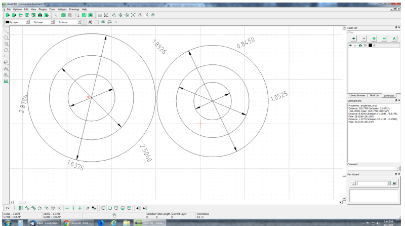
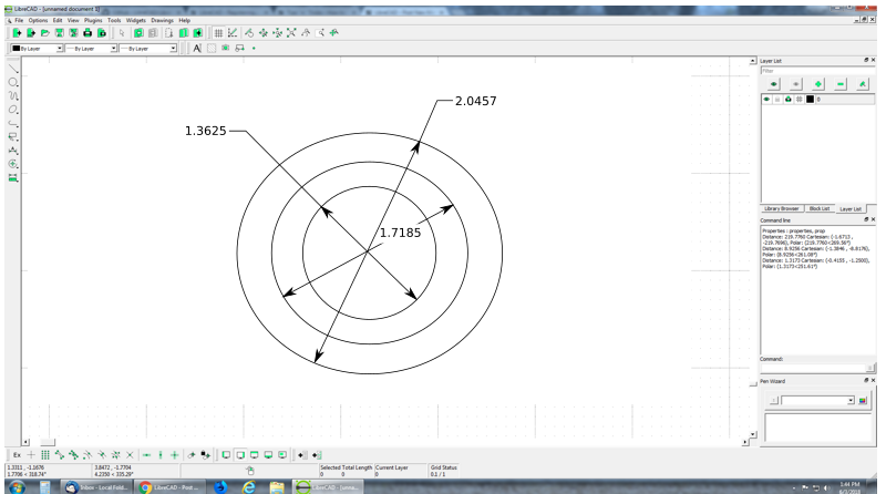
Dimension text should always be in-line with its leaders, without exception. Currently the behavior is that dimension text can be moved literally anywhere—clear across the drawing, if desired, and there's no visual way of determining which text belongs to which leader & arrows. This is not good: This really came down to bite me when importing heavily-dimensioned drawings from AutoCAD. Suddenly I had a lot of arrows, and a lot of text, and the only way to associate one with the other was to select them and see which changed color, which is not a useful workflow in printed drawings. Further, there's no way to clean up a drawing and make it easier to read by rearranging text and leaders. You can drag the text, but make the slightest change to the formatting, and it will snap back to the default position. It's very frustrating to try and make a drawing presentable. If the leaders were kept in-line with the text no matter what, this would not be a problem; drag the text, and it has the same effect as moving the blue dots on the leaders. Move the blue dots on the leaders, and it moves the text along with it. A leader line from the arrows should never end farther than a set distance from the text (probably equal to the keep-out distance when the text is drawn in between the arrows). If the text is dragged farther away, the extension line should be extended to reach it. They need to be tightly associated with each other to prevent the mess I illustrated above. Generally speaking, dimension text should be horizontal to the drawing, even for diametric, vertical, aligned dims and radii, and even orthographic views. This is standard practice in 2D drafting, and makes stacking dimensions considerably less messy (and honestly it should simplify the code, because text rotation is always zero). The only exception to this I've seen is incremental horizontal dimensions, where it is more compact to have the text aligned to the vertical leaders. For diameters and radii where the dimension text is moved outside the circle, a short leader should come from the text in the direction of the center of the circle (e.g. if the center of the text is to the right of the center of the radius/diameter, the leader projects to the left, and vice-versa—it's a simple X-comparison), and the tip of that short leader is considered the center of the text towards which the leader extension is drawn from the tip of the arrow, and towards which the arrow points. This is better: I'm not much of a programmer, but I've done quite a bit of 2D & 3D drafting over the last forty years. mostly in AutoCAD and SolidWorks. |
|
Hi Folks,
I'm a nOOb to LibreCAD, so please forgive me if this discussion is a rehash of known issues/features. I am running version 2.1.3 downloaded 27May2018 on WindowsXP, SP3. While LibreCAD overall is an excellent and useful tool that I was thrilled to find, there are a number of behaviors that strike me as counterintuitive. I am raising them here in the spirit of continued improvement. I have tried to find information on this forum about these issues but without luck so far, so if they have already been raised, please point me to the right thread. 1. Radial and angular dimensions always seem to be aligned with the leader and arrow rather than to the Text Alignment preference shown in the Dimensions tab of the Current Drawing Preferences dialogue box. Diametric and linear dimensions do follow the Text Alignment preference and change accordingly as that preference is changed. The latter behavior is preferable. 2. Radial and diametric dimensions and their leaders by default are always located inside the arc/circle. The text can be moved by the user, but the location of the leader and arrow is fixed to the default location. It would be better if the user could generally select the location of each measurement and the leader for all dimensions, e.g., specify the side of the arc where radial dimensions appear, or the side of the extension lines where linear dimensions (leaders, arrows and text) appear. The current behavior is often a problem, e.g., when dimensions inside a span are obscured by other dimensions, text, hatching, etc., or when dimensions are clearer when placed outside the span, or when dimensioning large-radius arcs, since the center of the arc can be far away from the rest of the objects in the drawing, causing the leader to run off the desired printing area of the drawing. 3. Though radial or diametric dimensions' text can be put wherever the user wants, if any property of a radial or diametric dimension is changed after the text is relocated, the text reverts to the default position instead of the location previously chosen by the user. Linear dimensions stay put when their properties are changed. The latter behavior is better, since it saves the frustration of having to reset the location of the text after each modification when you are experimenting to find the best way to show the dimension. 4. The position of angular dimensions cannot be readjusted once created, nor can the associated text be relocated. This is inconsistent with the other dimensioning methods. Also, it would be good if the measurement text's alignment and location could both be adjusted in the same manner as those of the other types of dimensions. 5. The following steps do not produce the expected behavior. They assume that drawings are stored in the Drawings folder on the desktop, while templates are stored in c:\Windows\Program Files\LibreCAD\resources\library\templates\, which is the setting for the templates path in Application Preferences. a. Start LibreCAD and create a new drawing. Save it to the Drawings folder. b. Invoke the "Open" command. The Open Drawing dialogue box opens and points to the templates folder instead of the Drawings folder. Navigate in the dialogue box to the Drawings folder and open a file. c. Invoke the "New From Template" command. The Open Drawing dialogue box opens pointed at the Drawings folder instead of the Templates folder. Navigate in the box to the Templates folder and open a template. d. Invoke the "Open" command. The Open Drawing dialogue box opens pointed at the Templates folder instead of the Drawings folder. Hmmm... It would seem more intuitive to have the "Open" and "Save As" commands pointing to the same directory (Drawings) and the "New From Templates" command pointing at the Templates directory, independent of where the other File commands are pulling data. I could go on, but this message is too long already, so I'll finish by recognizing resource limitations and that one person's bug may be another's essential feature. If the behaviors above are necessary for other functionality, then I guess I'll live with it, but if they can be changed in the suggested ways, it would be a useful refinement to LC (for me, anyway). Thanks! Chetan |
|
Administrator
|
@ctalwalkar, I moved your post, as the tenor about dimensions is nearly identical to Victor_Wren's post from yesterday.
About the new file/from template issue, I'll create a ticket on github to keep track of that. It's always better to keep different issues in separate threads, otherwise things may fall by the wayside. Also the chances to get replies is much higher when things are assorted. Armin
investing less than half an hour into Search function can save hours or days of waiting for a solution
|
|
Administrator
|
Follow up file open dialogs:
https://github.com/LibreCAD/LibreCAD/issues/987
investing less than half an hour into Search function can save hours or days of waiting for a solution
|
Re: Basic Dimensioning Functionality
|
Administrator
|
In reply to this post by Victor_Wren
@Victor_Wren, this first picture looks really weird, if this is the state after import, there may be some issues with different interpretation of DXF compared to ACAD. Then it would be good to have an original ACAD created DXF file for further investigations.
Follow up: http://forum.librecad.org/Inside-horizontal-dimensions-tp5715827p5715868.html
investing less than half an hour into Search function can save hours or days of waiting for a solution
|
Re: Basic Dimensioning Functionality
|
I just generated that inside LibreCAD to give an example of the issues. Basically I did a number of dimensioned concentric circles, then rearranged the text. Ideally, the leader arrows would always point at the text (and from the other discussion, it looks like that is well in progress in Master). The DXF imports of drawings I generated in ACAD are not quite so bad, but the dimension text can be quite far divorced from the actual leaders. Let me grab an example...
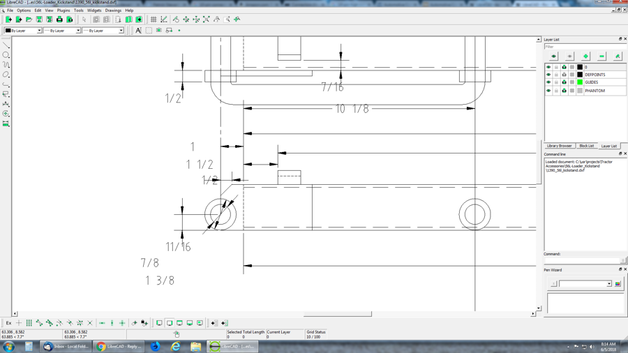
 Not nearly as bad as the version above that I deliberately screwed up, certainly, but less than ideal. The 1-3/8 leaders look like it should be an inside dimension, and the 7/8 diameter an outside, but both text elements have been evicted. In other parts of the drawing, the dimensions have flown off a goodly distance, and are displaced from the leader arrows enough that it's actually misleading as to which dimension belongs to which leader (which is kind of the opposite of the purpose of a mechanical drawing). I expect some clean-up issues on import, and frankly, I think LibreCAD is doing a brilliant job (even ACAD doesn't always import its own DXF files nicely). It doesn't help, I'm sure, that I'm actually having to process them through NanoCAD to get the DXF files, as I don't have access to ACAD at the moment. |
|
Librecad dimensions are very basic, and can only produce a subset of visual representations possible in autocad. I had worked on a few of those issues, and my progress was summarized in:
http://forum.librecad.org/Inside-horizontal-dimensions-td5715827.html I had made a proposal to improve dynamic leader extensions to model autocad in this comment: http://forum.librecad.org/Inside-horizontal-dimensions-tp5715827p5715868.html but the work has not started. Besides this, there are probably more things to fix. In short, even if we fixed any bugs (if there are any) related to DXF parsing, librecad just doesn't have a fully implemented dimensions, relative to autocad. |
Re: Basic Dimensioning Functionality
|
Thanks for all the work you've done on this so far! There's a ton of fiddly options in ACAD's dimension system that I haven't used once in the decades I've been using it and wouldn't miss (but I'm sure in specialized fields might be more useful).
The things I use most are the auto dragging, the ability to override the dimension scale on a per-use basis (for making things fit when I have detailed areas), the overall dimension scale factor, the precision on a per-use basis (on some of the heavy equipment parts I do, the precision of the large welded parts might only be ±0.1, but hydraulic attachments are ±0.001. I've also had sheet metal guys yell at me for specifying bends with too much precision, but the hole punch diameters HAVE to be and CAN be higher precision). I also frequently use the ability to modify the annotations to add extra information (such as "<dim> 3 Places"). I actually do use the ability to display in decimal, fractions (being still stuck with archaic American measuring systems) and ft/inches (as differing from just inches). The last one's pretty important for architectural use in the USA. (a fringe use would be "ft/miles" for people doing civil engineering). Also highly useful is the ability to have dimensions track a "stretch" operation, and to move the insertion points of the dimension to other details (such as if I initially use a "perpendicular" snap in the middle of a line, but change my mind and want to dimension from an endpoint to make the the leader gap visible). That's kind of my own personal "fantasy wish list." Some of this is already in LibreCAD (I think—I'm still learning my way around it). I am already happier with LibreCAD's approach to dimensioning as just another tool rather than a "mode" that precludes all other operations until you exit it (I still use ACAD primarily in command-line mode from long habit). |
«
Return to Suggestions & Feedback
|
1 view|%1 views
| Free forum by Nabble | Edit this page |

