DXF read gives only points, no lines 2.1.0
|
This post was updated on .
Using this
Version: 2.1.0 Compiler: GNU GCC 4.9.1 Compiled on: Jun 5 2016 Qt Version: 5.4.1 Boost Version: 1.53.0 System: Windows 8.1 When I read DXF files, there are no errors, but no lines appear, just points. Text is ok, Looking carefully, I can see points present for each entity, and zooming in, they look to be point-pairs, probably one line-width apart*. They are correctly scaled, just missing the lines ? Layers look as expected. So it mostly works, just renders in a strange manner. Very strange, and I see recent posts somewhat similar. DXF files are very simple outline drawings created from Mentor PADS via DXF Export. Attached are two small simple test files - Just Circle/Square/Text/& 2 polyline with ARC BoardOnly_mm_flat.dxf BoardOnly_mm_Full.dxf DXF files import fine into other CAD systems, and are a mature/older/stable DXF format. * I changed the line width to 1mm, and checked the point-pairs, which report 0.25mm, so they are line related, but strangely spaced at one quarter the line width ? Addit: As a workaround, I found if I download the old-but-good A9CAD and load DXF into that, (loads fine) then save-as, then the A9CAD dxf will then load into LibreCAD mostly ok. (seems to have line-width issues, but lines are all there) addit2: Looking at the fail/pass DXFs, I see the fail case uses SEQEND for the polylines, but the pass ones saved using a vertex pair. Maybe LibreCAD is not correctly handling the SEQEND structure ? http://www.autodesk.com/techpubs/autocad/acad2000/dxf/seqend_dxf_06.htm http://www.klayout.de/dxf_format.html ok: AcDbPolyline 90 2 70 0 43 1.0 10 5.969 20 3.429 10 5.08 20 4.318 0 LWPOLYLINE fails?: POLYLINE 5 2E 8 2DLINES_1 66 1 40 1.000000 41 1.000000 0 VERTEX 5 2F 8 2DLINES_1 10 5.96900 20 3.42900 0 VERTEX 5 30 8 2DLINES_1 10 5.08000 20 4.31800 0 SEQEND |
|
'board_only_mm_flat' at least shows lines in LC 2.0.11. Might be a hint for the reason. Unfortunately there is no dxf - specialist available at the time now.
|
|
This problem could be because of changes to libdxfrw.
https://github.com/LibreCAD/LibreCAD/commit/f7b4421b9d608d5bcb7b45ee5f8e6add81f7e73d?diff=split https://github.com/LibreCAD/LibreCAD/commits/master/libraries/libdxfrw/src/libdxfrw.cpp |
hmm, interesting, that does seem to have changed the phase a little around VERTEX & SEQEND ? The comment L2526 says //another vertex, but the code says v.reset(); The new code also seems to create a new DRW_Vertex{v}), even on SEQEND, which seems suss ? The DXF I have has 2 VERTEX and 1 SEQEND for one single XY line pair, so it should add only 2 vertex when called 3 times as VERTEX.VERTEX.SEQEND I do not know the whole flow, but I think it makes more sense to read nextentity, then do v = new DRW_Vertex(); as the DXF is like this = order is (code)(nextentity)(possible XY) and 0 SEQEND looks like it should be a pure exit-done (old code looks ok ?) I wonder what this was trying to fix - was there a specific DXF parsing issue ? The title says only fixed a potential memory leak ? cleaned DXF version, that still fails : 0 POLYLINE 8 2DLINES_1 66 1 40 1.000000 41 1.000000 0 VERTEX 10 5.08000 20 43.18000 0 VERTEX 10 5.96900 20 44.06900 0 SEQEND |
|
This post was updated on .
I haven't worked with DXF much.
I could help you get started with tweaking the code... https://github.com/LibreCAD/LibreCAD/wiki/Git-and-GitHub https://github.com/LibreCAD/LibreCAD/wiki/Build-from-source https://github.com/LibreCAD/LibreCAD/wiki/Becoming-a-developer (see the Code Navigation section) |
That makes two of us :) I can barely read DXF, and I expect it to just load... |
|
Your comment about .reset() helped...
It looks like there was some confusion because DRW_Vertex and shared_ptr both have reset() The following change seems to solve the problem: v.reset(new DRW_Vertex); //another vertex |
That was lucky :) - there is also a march 23 code which seems around shared pointers, not logic changes, not sure where that is in the mix too... |
|
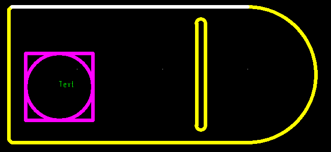
I'll add a screen capture of what that file should look like, so you can confirm the fixes.
Selected line is 70.231mm and widths are 1mm  better add the exact test file too.. BoardOnly_mm_W1_Flat.dxf |
|
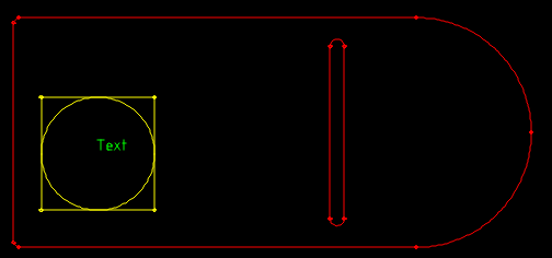
Everything is drawn, but it looks like:

|
|
This post was updated on .
Here are 2 more test cases.
( tested in kiCAD which I think uses this same DXF engine, they do not import the same) QCAD_R27_2013_1mm.zip The LWPOLYLINE R27 imports ok and the POLYLINE form, R9, drops the circle and arcs. Can you confirm both these can import into LibreCAD ok, with Arc/Circles as in your image ? (oops, almost as in your image, I see I dragged an ARC on RHS of the square in QCAD) To me, that is good :) ARC and circle preserve is the most important. Line width is nice to preserve too, as sometimes that has information, but less important. DoubleCAD opens QCAD_R9_2013_1mm.dxf with re al-line width display, but has issues with R27-maybe too new ? A9CAD opens R9, with no width (ie same as your image), but fails R27, no surprise as A9CAD is 2005 dated. Addit: Just checking on Width, Straight lines W=1mm, and Circles W=0.5mm, but not drawn as circles, - seem to be as two diameters, with a bulge of 1, for two half-circles. Manually editing those widths to 1.0 and 0.5 then renders ok. eg X ends of 5.719 - 6.219, when bulged give a centre of 5.969 |
|
In reply to this post by ravas
Seem this fix did not make it into -40- build ? Can you please post a message when a build (win64) is available that includes this fix, & I will exercise it... |
|
It will be in alpha-45.
|
Thanks, tested that, and it does looks to have fixed the dot-issue :) LC can now import DXF files saved from PADS / DoubleCAD / A9CAD / QCAD, and files LC exports can import into PADS and DoubleCAD. The real line width is not preserved, but that is less important than the polyline info. |
«
Return to LibreCAD-user
|
1 view|%1 views
| Free forum by Nabble | Edit this page |

