Double lines and unwanted connections

Previous Topic Next Topic
 
classic Classic list List threaded Threaded
7 messages Options
Reply | Threaded
Open this post in threaded view
|

Double lines and unwanted connections

marcin
Dear LibreCAD community,

so I've got this dxf exported from a commercial cs cad tool dxfDoubleLine.dxf .

When opening it in LibreCad I see some strange things going on. The curved lines seem doubled


and there are straight lines connecting the corners


When uploading this dxf to an online dxf viewer (sharecad.org) I get the correct and expected results


I have experienced this with LibreCad 2.1.3 on Windows 10 as well as Arch Linux.

So what is going on here? Is this a bug in LibreCad or is the dxf faulty/not up to standard?
(Btw. PCBNew in KiCad exhibits exactly the same behavior. Does this point to a problem with libdxfrw?)

Regards

Marcin
Reply | Threaded
Open this post in threaded view
|

Re: Double lines and unwanted connections

aman
https://dokuwiki.librecad.org/doku.php/usage:faq#the_dxf_import_process_failed_why


It's  quite common some commercial cads have many option that LibreCad does have not.  
Reply | Threaded
Open this post in threaded view
|

Re: Double lines and unwanted connections

marcin
Thanks for that reply. I'd like to suggest a feature request for LibreCad to issue a warning every time it encounters a dxf version/feature it does not understand, preferably mentioning a link to the explanation of the problem in the forum.
Reply | Threaded
Open this post in threaded view
|

Re: Double lines and unwanted connections

LordOfBikes
Administrator
Marcin,

your DXF contains special polylines. It needed some investigation to figure this out.

What LibreCAD shows are the vertices contained in these polylines. So basically I think libdxfrw reads the DXF without issues. But LibreCAD seems not to interpret the special flags set on the vertices.
From the polyline flags I suppose the vertices should be used to create a spline and they represent fit or control points.

The DXF is really old. AC1009 is DXF R11/R12 format and thus pre 1995!
It lacks many information, like variables and tables.

Because R12 has no support for SPLINE entities, I come to the conclusion that this was the early way to save splines in DXF before 1995. The R13 format, released 1995, brought SPLINE support, thus I assume polyline splines are deprecated, even when they are still contained in modern DXF reference.

In fact I've never seen this before, it must be a rarely used feature. And it is not implemented in LibreCAD.
Possibly it was never implemented because it was already deprecated when LibreCAD begins.
investing less than half an hour into Search function can save hours or days of waiting for a solution
Reply | Threaded
Open this post in threaded view
|

Re: Double lines and unwanted connections

marcin
LordOfBikes,

The DXF is really old. AC1009 is DXF R11/R12 format and thus pre 1995!
I decided to investigate this a bit more. According to https://www.loc.gov/preservation/digital/formats/fdd/fdd000446.shtml  AC1009 has been published together with  AutoCAD Release 11 which, according to https://autodesk.blogs.com/between_the_lines/autocad-release-history.html has been released 1990. So yes, it is ancient.

It lacks many information, like variables and tables.
 Does this mean, it is broken or invalid?

 your DXF contains special polylines. It needed some investigation to figure this out.
I am new to dxf and curious how you went about investigating this issue. So if you cared to leave some hints or directions on what steps you have taken here I'd appreciate that a lot. :-)


In fact I've never seen this before, it must be a rarely used feature. And it is not implemented in LibreCAD.
The orogin of this dxf file is a big commercial cad software package which is very popular within the engineering industry. Therefore I'd expect this kind of issues to come up more often in the future. So I feel it is even more important to let LibreCad issue a warning when it encounters this kind of old cruft. Pointing blame in the right direction should help reduce frustration and support requests in the LibreCad forum.


Anyway, thanks a lot for your support.
Reply | Threaded
Open this post in threaded view
|

Re: Double lines and unwanted connections

marcin
In reply to this post by LordOfBikes
Here I have used the ODA File Converter (link is in aman's comment) to convert the original file to more modern versions. I got
dxfDoubleLineAC1018.dxf and dxfDoubleLineAC1021.dxf.

Both these files show the same problems in LibreCad: double lines and unwanted connections. ;-(
Reply | Threaded
Open this post in threaded view
|

Re: Double lines and unwanted connections

LordOfBikes
Administrator
As I said, the original file contains valid DXF information which is still valid in newer DXF formats.
Thus it's not surprising, that upgrading the DXF version does not change the results.

You asked for details about my investigations. It is as simple as open the DXF file in a text editor and use an appropriate DXF reference to understand the content. It helps when doing this regularly, but it's not rocket science.

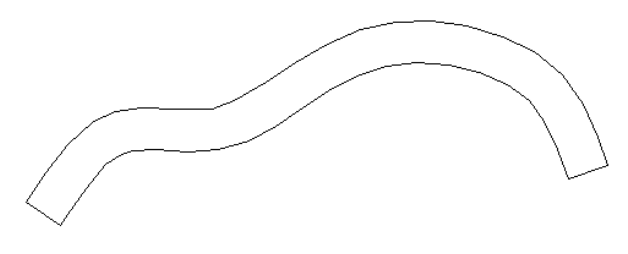
I opened the file in Autodesk TrueView for reference. It shows kind of your expected result.
I say kind of, because it is also not what I'd expect from my DXF reference studies.

What I recommend is:
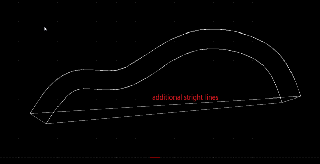
- explode the polylines
- separate the doubled contours, best is to move on new layers
- optionally make polylines from separated contours again
- create the spline from separated contours

To detail my recommendation, I did some more investigations.
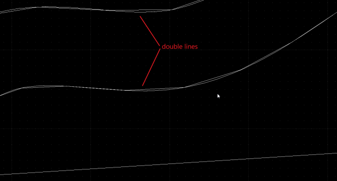
- The DXF contains 4 POLYLINE entities, 2 curves and the 2 straight connection lines.
- The curves are doubled because they contain two kinds of VERTEX entities.
- Each curve has well over 20 VERTEX entities representing points on the spline-fit POLYLINE (what TrueView shows)
Code: 70
Value: 8
- Each curve has about 160 VERTEX entities representing control points, defining the spline frame
Code: 70
Value: 16

So the truth is somewhere in-between, both halves do not show the intended curve.
Depending on the required tolerance the ~160 vertex contours are already good approximations.
For the exact splines use Snap on Endpoints only and select the curve to follow.
This makes it easier, to follow the selected curve points (blue).
To create the spline use Tool->Curve->Spline through points and follow the ~20 vertex contour.
Or with Tool->Curve->Spline you have to set Degree to 2 and follow the ~160 vertex contour.
investing less than half an hour into Search function can save hours or days of waiting for a solution