Isometric drawing dimension

Previous Topic Next Topic
 
classic Classic list List threaded Threaded
9 messages Options
Reply | Threaded
Open this post in threaded view
|

Isometric drawing dimension

Rock77
Let me start by praising to the developer and the community of LibreCAD for the wonderful tool and knowledge they provide for free.

I am a mechanical engineer with limited experience in CAD and professional drawing and I would like to understand if there is an easy way to generate in librecad the dimensions for an isometric drawing as the example in the following image:


I did some experiment with the aligned dimension, but in order to have the text and the extension lines aligned to the isometric axis I need to explode the dimension and manipulate each single object (that is at least time consuming)

Is there any option that I am missing, or any plan to further develop the dimensions commands to simplify the annotations on isometric drawing?

Reply | Threaded
Open this post in threaded view
|

Re: Isometric drawing dimension

fa201
Digging into the documentation, I found the following which could help :
https://wiki.librecad.org/index.php?title=LibreCAD_users_Manual#Isometric_Grid (old wiki for old GUI but the principles should be the same).
https://librecad.readthedocs.io/en/latest/guides/dwg-edit.html?highlight=isometric#isometric-view
Fabrice

French hobbyist interested in 2D design.
Reply | Threaded
Open this post in threaded view
|

Re: Isometric drawing dimension

Rock77
Fabrice, thank you for the hint,
the wiki references are useful but maybe I am still missing something: this is the result I was able to get in LibreCAD


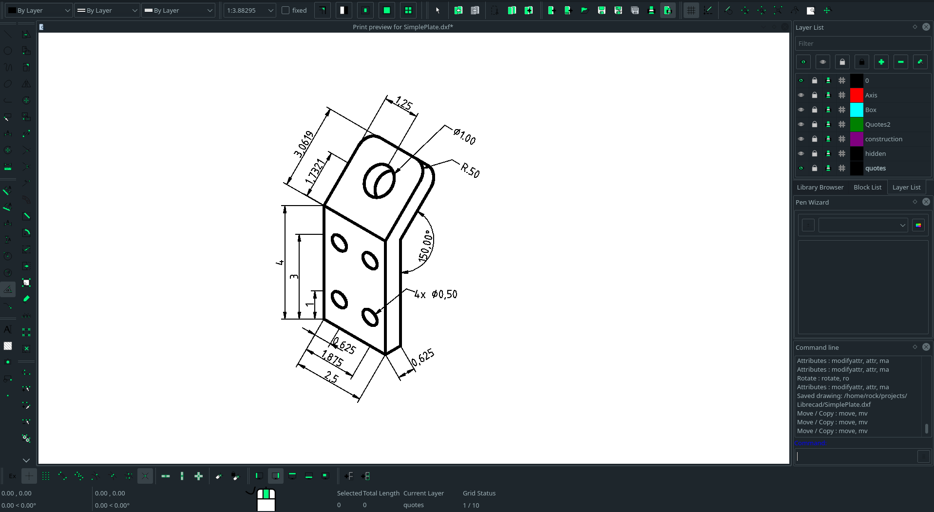
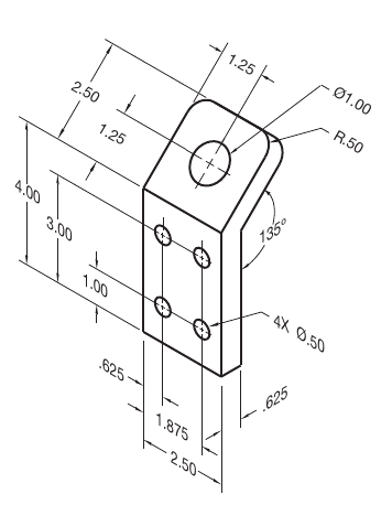
As you can see from the comparison of my drawing with the reference image, the lenght of the upper piece of the plate are wrong (even if the drawing is dimensionally correct), since the lines are drown along an isometric axis

The angular dimension is also wrong (150° is the value in the plane of the paper, but the actual value in the isometric view should be 135°)

Finally the extension lines are not following the isometric axis, but are just orthogonal to the lines in the plane of the paper

As I said, all those things could be fixed exploding the dimensions and working manually, but of course this approach is time consuming and increase the possibility to make a mistake
Reply | Threaded
Open this post in threaded view
|

Re: Isometric drawing dimension

dellus
What you want can not be done in LibreCAD.
The screenshot of the example you show probably has been made from 3-D CAD program where you can draw the dimensions in the according views / planes and then turn the whole thing into an isometric view.

The length of the upper piece of the plate probably is right, just draw a line parallel to the bending edge with a distance of 2.5 units and see where it lies. The angle also is indicated properly, as LibreCAD is a 2-D program and can't know what the angle would be in a straight side view.
The isometric grid is just an aid to easily draw 30/60 degree lines, but you can't really draw these with 3-D coordinates.  

 
pt
Reply | Threaded
Open this post in threaded view
|

Re: Isometric drawing dimension

pt
In reply to this post by Rock77
my 3 views

I am wondering how the bending of the metal around an angle changes the dimensions either on the outside of the bracket of on the inside of the bracket.
Thus the intended hole at the top may be affected by this effect.
See this photo.

I agree isometric is confusing and likely not an appropriate view for this part (not needed).

p.s. I am new to librecad ... I drew the part 10:1 scale and then when I added the dimensioning notes
the numbers are 10 times too large.  Is there an easy way to scale the image without shrinking it 10 times?
Reply | Threaded
Open this post in threaded view
|

Re: Isometric drawing dimension

flywire
pt wrote
I am wondering how the bending of the metal around an angle changes the dimensions either on the outside of the bracket of on the inside of the bracket.
You will bend inner and outer it around a radius, with the minimum radius dependent on the material and it's thickness, so there will be no sharp angle on the inner radius.
Reply | Threaded
Open this post in threaded view
|

Re: Isometric drawing dimension

dellus
In reply to this post by pt
Scaling:
The normal procedure is to draw in 1:1 scale, real life size. Scaling the drawing up or down is then done in the print process, in Print Preview.
If you insist on scaling when drawing, you can manipulate the reading in the dimensions in Options - Current Drawing Preferences - Dimensions - Length Factor. But if you check a length with Measure it will show the length as drawn. It is not a recommendable way.
pt
Reply | Threaded
Open this post in threaded view
|

Re: Isometric drawing dimension

pt
OK ... yes I agree, the inner bend needs a radius to bend around.
The outside corner will naturally be that radius plus the thickness of the metal,
(although in reality it may flatten a tad bit).

The original author did not show this effect thus leading to my question.
The bending distorts the outside measurements.

The side view makes this point clearer and begs the author to determine how he
wants the design to be done.

I can measure the lengths of the vertical, the bend and top angled lengths, but
does it make sense to show this dimension on the left side of the front view?
Probably not.
pt
Reply | Threaded
Open this post in threaded view
|

Re: Isometric drawing dimension

pt
In reply to this post by dellus
Thank you for answering this comment.  I found the units and scaling operation very confusing.

When I started drawing the part using a setup I had done for a more reasonable design size, I noticed that the thickness of the lines were too large and difficult to visualize.

I used the scaling function on a copy of this design and shrunk everything down by a factor of 10.
Again the line sizes were WAY TOO BIG and after adjusting them in the layer settings, I found almost no
reasonable looking view.  All the text was crammed into an unreadable form.

Maybe the part is too small but yet is a good example of "beginner fright" and a "lack of drawing experience".

My background is in micro semiconductor layout drawings and we over the years went from drawing things in microns to nanometers.  Nothing was ever drawn 1:1

I will experiment with "Drawing Preferences" a bit more.  It wasn't obvious I was doing anything correctly in that menu either.

I am impressed with the programs excellent features.  I particularly like the snapping functions and the relative drawing features.  Although I noticed when trying the 2nd point on a rectangle using the @ relative designation, the rectangle was drawn in the wrong location.  (also when I went to divide it ... I could not do it ... until exploding it!)

Keep up the excellent work!