One dxf, two cads see different things -hiw to resolve?

Previous Topic Next Topic
 
classic Classic list List threaded Threaded
7 messages Options
Reply | Threaded
Open this post in threaded view
|

One dxf, two cads see different things -hiw to resolve?

Buntehuhn
Kindly requesting your help to use LibreCAD to resolve this issue.

Situation:
I want to lasercut parts for a model glider, from 2mm plywood, at the fablab nearby. The fablab accepts dxf-files as input, the fablab's laser-software is then used to create gcode.
The design is created in a specialized model plane 3D cadprogram, devwing, and exported as a dxf-file.
With LibreCAD I've opened the devcad-dxf and saved the parts (two ribs) to be cut from 2mm plywood in a separate dxf-file, for the fablab to check if it is suitable for the laser-software. They check that using CorelDraw, I think version 2007 or 2017; anyways, a nvory much not recent version, but definiy suitable for their compatabilty-check.

The issue
The file I supply, the attached Amokka Finparts triplex2mm, contains two ribs, with the top one containing two round circles (that will become holes)
The fablab sees not those round circles, but sees each circle as two overlapping ellipses: see attached image What fablab sees_Amokka Finparts triplex2mm.

What I want the fablab to see, are the two round circles.

My questions
1. How can I make those ellipses in the file that I supply, visible in LibreCAD?
2. How do I then adjust my librecad-dxf so the fablab sees what I want it to see?

Kind regards,
Arjan
Amokka_Finparts_triplex2mm.dxf
What_fablab_sees_Amokka_Finparts_triplex2mm.png
Reply | Threaded
Open this post in threaded view
|

Re: One dxf, two cads see different things -hiw to resolve?

LordOfBikes
Administrator
Welcome Buntehuhn!

Using the plugin 
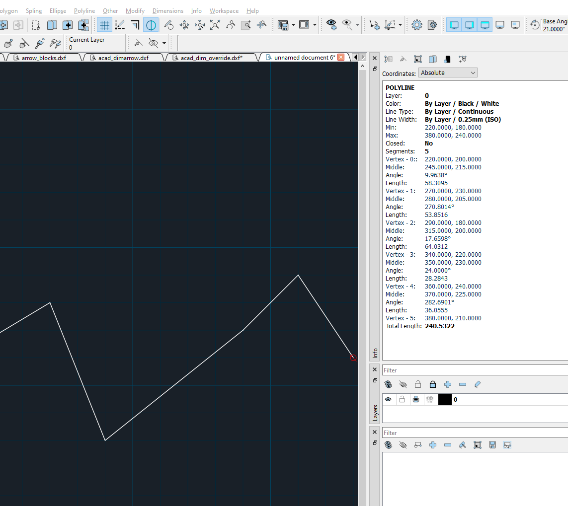
List Entities you can check the situation.

First, there are 2 overlapping blocks. The whole fin is from block *R and the 2 holes are overlapped by block *R 2 which is the single hole.

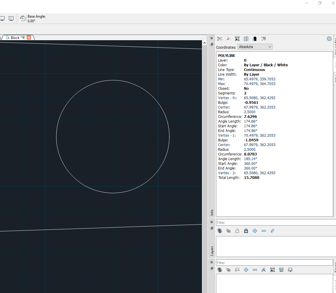
Both holes, in block *R and *R 2 are built from a POLYLINE. This may be because there is already a defined contour for CNC router or laser cutter. A CIRCLE entity is just defined by its center and radius, what is good for drilling, but not for milling or cutting.

So basically the only problem I see is the overlap. Move the fine and you will see the remaining circles to delete them.

Concerning what fablab sees, I think that LibreCAD is correct and fablab wrong. The circle POLYLINE has 3 vertices, start, opposit and end. Start and End are the same point, so it is a closed entity. The distance from start/end to opposite is 4.9949 and the radius of the 2 semicircles is 2.5. So this is nearly a perfect circle.
The problem is, that the radius is not stored in the DXF file, there is some weird formula to calculate the radius from a parameter in the POLYLINE named bulge.
So I suspect, that the fablab software has an issue with that.

You can try to replace the POLYLINE circles in your drawing with real CIRCLE entities to check what fablab sees then. If this fails too, they might have an example DXF for you with circles to see what it needs.

Good luck!

Armin
investing less than half an hour into Search function can save hours or days of waiting for a solution
Reply | Threaded
Open this post in threaded view
|

Re: One dxf, two cads see different things -hiw to resolve?

Buntehuhn
In reply to this post by Buntehuhn
Thank you very much Armin!
I'll try that as soon as I'm near my laptop again, and inform you here of the results.
Kind regards,
Arjan
Reply | Threaded
Open this post in threaded view
|

Re: One dxf, two cads see different things -hiw to resolve?

Buntehuhn
I tried to use the List Entities plugin, watched how-to videos and read forum posts about its use. My LibreCAD & dxf-file result in no information on entities.
How do I get this plugin to work?


I'm using LibreCAD 2.2.1.1
What I've tried:
1. Unselect all / Select an object / select plugin List Entities / Enter > no information is shown, the selected object stays selected;
2. Unselect all / select plugin List Entities / select an object / Enter > no information is shown, the selected object stays selected.

Reply | Threaded
Open this post in threaded view
|

Re: One dxf, two cads see different things -hiw to resolve?

sand1024
in order to investigate polyline vertexes you can use a bit different approach.

1) download 2.2.2 alpha version - https://github.com/LibreCAD/LibreCAD/releases/tag/2.2.2_alpha-latest
2) there is "Info" widget
3) Enable it
3) Using this widget, you can select the entity you're interested in and inspect it's properties (including vertexes coordinates for polyline)

It will be something like this

Reply | Threaded
Open this post in threaded view
|

Re: One dxf, two cads see different things -hiw to resolve?

sand1024
indeed, it seems that polyline is handled correctly in LibreCAD. Here are more details for the cycle from your drawing (located in block *R) that is modelled by polyline

Reply | Threaded
Open this post in threaded view
|

Re: One dxf, two cads see different things -hiw to resolve?

Buntehuhn
I downloaded th ealpha-version but cannot install it.
I'm afraid this pinballing process of one step ahead and many back, to slightly modify a dxf-file, is too demotivating for me.
I'v purchased QCAD, hope that has an onboarding process that suits me better.
Even so, I very much appreciate both your efforts to help me getting LibreCAD to work!

Kind regards,
Arjan