repositioning dimensions and saving individual layers
|
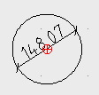
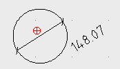
New LibreCAD user here. A couple of questions. I am running the latest version on a Mac OS 10.12.6. When I add dimensions and later want to move the text to a new position (especially with diametrical dims) I can't seem to find the secret command. If I select the text, the entire dimension is selected and I can move the it as a unit to another location (why anyone would want to do that I don't know). If I explode the dimension first, I still can't seem to move the text to another location to make it more readable.
I am using the app to create PC board outlines which I need to import into KiCAD. It appears according to KiCAD that I have to save the files as R12 dxfs after exploding the entire drawing. When I do that and then reopen the file in LIbrecad there are a bunch of lines on the dimension layer originating at the origin and going out to the dimension lines which are not there before I save it as an R12 file. Then when I import the file into KiCAD I get all the layers and it gives me no way to just select the drawing layer so I am wondering if its possible to just save the one drawing layer as a dxf to exclude dimensions and construction layers? |
Re: repositioning dimensions and saving individual layers
|
Administrator
|
Welcome PhilG!
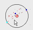
To move a dimension label, select it and then find the little blue square, bottom left of the label. Left click and drag the blue square, then you can release the mouse button and move the lable. Left click again to place the label at its new position. This trick works for most entities, e.g. to move line endpoints, polyline vertices or resize circles. You can't save or export single layers in LibreCAD. You have to delete the unwanted layers and save the file with new name for the KiCAD import. Iirc, there was an issue with erroneous lines from the origin, related with dimensions. I know it was fixed, but I can't remember the exact circumstances and version when it was fixed. I have to search in history when this is relevant. Armin
investing less than half an hour into Search function can save hours or days of waiting for a solution
|
|
Thanks Armin.
So I tried repositioning a linear dimension and when I click on the dim text it selects all the dimension lines associated with that text. There is, however, a little blue dot in the text which, when I do what you described does move the text without moving the dimension lines. But, when I try that with a diametric dimension there is no dot in the text and any movement moves the lines, arrows and text to another point! If I explode the dimetric dimension first then there is a dot and I can move just the text. The erroneous lines seem to be related to saving the file as an R12 file. A simple save and reopen does not cause that problem. The KiCAD docs say that KiCAD can't handle polylines. Are circles of parts of circles considered polylines? I will take your suggestion and delete all layers except the part drawing and save that as such and give it a try. Phil |
Re: repositioning dimensions and saving individual layers
|
Administrator
|
Phil,
this is why I wrote works for most entities and not all. There may be more entities which are still not fully implemented, like diametric dimensions. Of course you can use explode, but this destroys any relation between the dimension entities. There is only a bunch of unrelated lines and text after explode. Another option would be to delete the label text with Tools/Modify/Properties tool. Enter a blank for the label and the dimension label will be invisible without exploding the dimension. Then you can place a MText with the diameter wherever you want. But you have to care about the style and size yourself, it is not taken from drawing preferences for dimensions. I had a look at closed issues, but it seems I mixed up some things. There was an issue with dimensions and zoom, where erroneous rectangles were drawn from the origin. And another issue with erroneous lines to the origin, but this was caused by splines. So if it is possible, can you post a drawing in standard DXF 2007 format and same drawing in R12 format which shows the issue? You can use the More button in your reply to upload files here. Basically a circle or arc can be a polyline. It depends on the used tools. Normally lines and circles are created with the corresponding tools from Lines or Circle menu. And polylines are created with Polyline tools. They create a continuous contour with lines and circular arcs. But there is also the tool Create Polyline from Existing Segmants which can convert single lines/arcs or multiple connected lines/arcs into a polyline. Armin
investing less than half an hour into Search function can save hours or days of waiting for a solution
|
|
In reply to this post by PhilG
For me, moving the text out of a diametric dimension works, V 1.2.3 Win XP.
   Polylines can mean not only a unit of connected elements, but also kind of a set of double lines, even with variable width between them, and a fill between them. LibreCAD doesn't have this feature. This feature might have been used do draw a pcb with wide tracks, so there is the warning that KiCAD can't handle that. |
|
In reply to this post by LordOfBikes
I have tried with your file and made a diametric dimension on one of the other mounting holes: the blue square is there, but hard to see as it lies exactly on the rim of the hole.

|
|
In reply to this post by PhilG
In LibreCAD 2.1.3 these erroneous lines indeed appear after saving as R12. As R13 it's ok.
In later RC 2.2 versions this bug seems to have been fixed. But while experimenting I have experienced that in the latest RC 2.2 you can only provoke the "save as" input and version selection box if something has been changed in the drawing. So you can't use it to just convert to a different version. New bug... |
«
Return to LibreCAD-user
|
1 view|%1 views
| Free forum by Nabble | Edit this page |

