Bug with Line and Circle Intersection, mismatch on snap Intersection
|
Hi,
On Feddora 29... Version: 2.2.0-rc1-105-gc2635841 Compiler: GNU GCC 8.3.1 Compiled on: Mar 6 2019 Qt Version: 5.11.3 Boost Version: 1.66.0 Create a new drawing - just two objects: set snap on grid draw a line: 2 points 0,100 100,70 draw a circle: Center, Point 0,100 100,100 # Line and circle intersect (visually) set snap on grid off, set snap Intersection on #Try to draw a line starting at the intersection of line and circle. # Zoom in (quite some way). # The starting point will appear over the line but off the circle circumfence by 0.0189 units. |
Re: Bug with Line and Circle Intersection, mismatch on snap Intersection
|
Administrator
|
Many thanks for elaborating and reporting this.
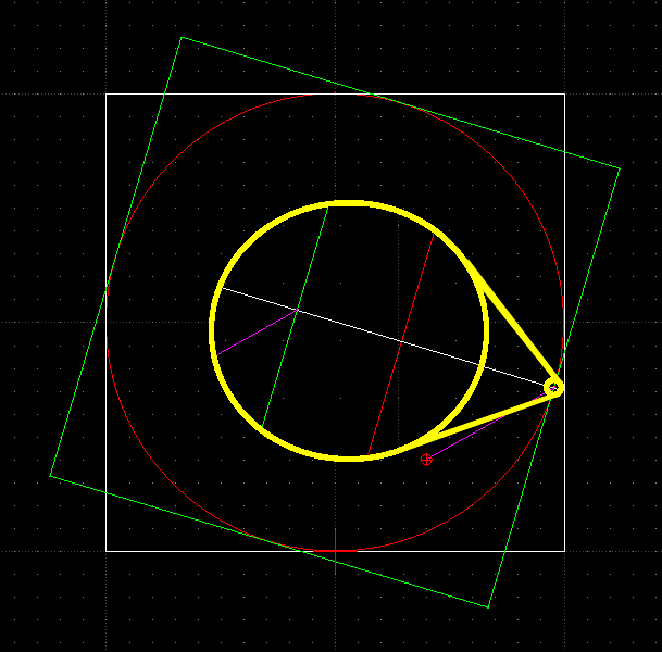
I wouldn't go this far and call it a bug. As you recognized yourself, you have to zoom in really deep to see this. This gap is way beyond a line width on printings or a realistic production tolerance. My first thought was a tolerance issue, as floating point math in computers is far away from exactness. Then I trimmed the line by the circle and checked the entities with the list plugin. Both are listed correct, the trimmed line length was 100.00 and the radius too. And there was the same gap between the line end and the circle. Now I created a square around the circle. It touches the circle on all 4 poles at 0°, 90°, 180° and 270° without any gap, even on deep zoom in. Also the grid was fine with the circle's circumference at the 4 poles. At least I rotated the square by the angle of the line. This showed me, that the end of the line is the correct position, because the square hits the line end and not the circle. More rotating brought me to the conclusion that the circle is drawn with some tolerance. Every 45° the circle match fine with the square. In between, at 22.5° the gap reach its peak with 0.02. Iirc, the cosine/sine methods, which apply for these kind of math, are simple tables under the hood. This may explain this effect. So finally its a tolerance issue from painting engine or how the painting engine computes the pixel from circle data (center, radius), but I can't say from memory who is responsible for this at least. I assume that we don't compute entity pixels positions inside LibreCAD, this would be done in a 3rd party library. I can't see a reasonable solution for this issue. Reaching out for more accuracy will impact the performance or bring other drawbacks, if it is possible at all. Anyway a nice catch to show difference between theory and practice. And here, as a picture is worth a thousand words  
investing less than half an hour into Search function can save hours or days of waiting for a solution
|
|
Thank you for the detailed information.
I did some geometrical drawings and was surprised to see a tangent not in it's place. This was noticeable at a moderate zooming factor. That is, one drawing unit resolution across the canvas. To snap onto the 'right' point, I zoomed in further and got to
the two entities in two places were I expected them in one place. (Actually in my case I had two circles, two tangents intersecting
in one point and this 'point' shows up as rectangle.)
I agree, that for practical purposes, printing at a high scale,
those deviations are irrelevant. However dealing with drawings where a higher resolution closeup is required, printing the details might become problem.
I propose to change this 'bug' into a feature request to add an
adjustable drawing preference: 'Re-calculate nonlinear objects (circle, .. ) representation
with higher precision when using high zoom-in factors.' It keeps the entity representation exact within the
representation space and it allows precise printing at lower scale factors. Add a selection: Representation precision increases when zooming in. Alt.: I suppose an additional entry in - Drawing Preferences - Splines Tab: Number of segments per circle _____ could do the job too.
Thank you again. HP
Am 06.03.19 um 16:30 schrieb
LordOfBikes [via LibreCAD]:
Many thanks for elaborating and reporting this. |
| Free forum by Nabble | Edit this page |


