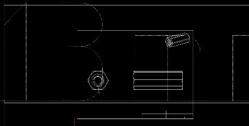
I think my entire drawing is VERY small. Can't find a 'Scale' function?
|
I started with an existing .DXF file, needing to "simply" change some measurements on there and add a "not to scale" tag.
I left the Text and MText Height at 1. Typed my text, clicked, and it dwarfs the drawing by multitudes. I also set the linewidth default from 0.00 to 0.13, and now when I click out of Draft mode, my drawing is just giant globs of white. So figuring my drawing might be unusually small, I did both the Export to PDF and Print to PDF. In both cases the PDF file appears blank. I read in another thread here about a 'Scale' function, but I am overlooking it, and not sure if it would even help here. The coordinates grid in the lower left show one corner of the drawing starting at 0.29 (upper left of drawing) and ending at 1.25 (upper right of drawing). I'm now guessing this is in inches? If my assumption is correct, how can I "blow up" my drawing? Pictures below for fun:   Thanks everyone |
|
It looks like your part is rather small. Line widths then appear very thick in comparison.
It's a matter of print scaling and other settings. Is the drawing made in inches, mm or what? What should be the print scale? Best if you provide the drawing file here with 'More v' - 'Upload a file'. |
|
Thank you. I've attached a version of the file a few saves before the one I butchered.
The part is a "simple" hex standoff. The units that were used in this drawing are in Inches, and I needed to update them to being in Metric, with a text box someplace that would say "not to scale", along with the usual criteria for the manufacturer. Here's the measurements and notes I wanted to add. If there's an easy way to increase the size of my drawing so I can properly insert the text, I would appreciate any direction. Thank you. EDIT: Sorry, I didn't answer your question on the Print Scale. Given the size of the part is only 17mm long, I figured an appropriate print scale would be 1:10, though I am open to suggestions. Given the simplicity of the part having it print out and fit nicely on a standard sheet of 8.5x11 paper should be sufficient. External shape: Hexagon ID M8x1.25 OD 13mm Length 17mm NOTES: 1. Material: Stainless Steel 2. ASME Y14.5M – 2009 3. All Dimensions are in Millimeters 4. Remove burrs and sharp edges TOLERANCES: ALL DIMENSIONS ARE MILLIMETERS (UNLESS OTHERWISE SPECIFIED) LENGTH: ± 0.005 DIAMETER: ±0.005 INTERNAL THREAD: Fully threaded |
|
There is no attached file, maybe you have not done it right.
Generally the problem is it will be an enlargement scale, where LibreCAD has a problem with linewidths becoming too thick in normal drawing view. You can switch to Draft mode, but then you cant see the text... In Print Preview you can see it right. In the latest development release there is an option to deal with the problem. It's still not clear what units you really use in your drawing. I have made a sample file assuming it's still inches. I think 5:1 is an appropriate scale I have to leave the house now, more later, when you have successfully uploaded your file. mech_inch_5_1_letter.dxf |
|
Custom_Hex_Standoff_v3.dxf
Thank you. I'm not sure what happened last time. I did it again here. It does insert some code at the top of the post with the filename. I thought it did this last night. Maybe I deleted it by accident when I was editing my reply. |
|
I have tweaked the drawing to fit on letter at scale 1:10, changed some linewidth settings, otherwise have left it as it is.
In normal drawing view lines look too thick, 10 times thicker. In Draft Mode they appear as hairlines, but sadly text is simplified to boxes then. In Print Preview it looks right. Custom_Hex_Standoff_v3_mod_letter.dxf |
|
Thank you very much!
Can you tell me how you changed the scale? |
|
I did not change the scale of the drawing's contents.
As 10:1 is an enlarging scale, the letter size frame has to be drawn 10 times smaller than in real size. In Print Preview you set 10:1 and in the print out or pdf it will be true letter size again. |
|
That is brilliant, thank you!
I was able to clean up the text a bit more by messing with the linewidth, and when I set text I just started bumping down the size, for some of it I used 0.02 and in other parts 0.015, and it worked out really well. I did the "Print" to PDF function, and the PDF came out great. Thank you for your help, and taking the time to work on this! |
|
In reply to this post by Trinten
Hi, I am newbie here.
I have a question. How to make a dimension if in one page, there are two drawing that have different scale. One drawing is a plan drawing. Scale 1:100 And another is a detail drawing. Scale 1:20. Thanx a lot. Regards. |
|
TLTR: the support for views is missing.
There's a proposal for allow editing a dimension to support function evaluation, like {10*<>} would be showing the measured value by 10 times of it. The feature is not implemented yet. The feature request is here: https://github.com/LibreCAD/LibreCAD/issues/1953
|
«
Return to LibreCAD-user
|
1 view|%1 views
| Free forum by Nabble | Edit this page |

