Inside-horizontal dimensions

Previous Topic Next Topic
 
classic Classic list List threaded Threaded
13 messages Options
Reply | Threaded
Open this post in threaded view
|

Inside-horizontal dimensions

sankey
I'm currently working on refactoring the code which draws dimensions, primarily to fix the appearance of "inside-horizontal" dimension text (aka.  "unidirectional", or just "horizontal").  In AutoCAD, inside-horizontal is the default dimension text style for imperial drawings, whereas "aligned" is the default for metric drawings.  LibreCAD uses aligned by default for all drawings, and for good reason: inside-horizontal is only partially implemented, and is pretty broken for linear dimensions.

This shows the basic difference between inside-horizontal and aligned styles:


Inside-horizontal mode is toggled by the DXF group code $DIMTIH (Dimension Text Inside-Horizontal), and the style is generally more palatable for viewing drawings on stationary computer monitors.  McMaster-Carr technical drawings are all rendered with inside-horizontal style dimensions, metric or not.  I'm particularly interested in it because I just really like how it looks.

There's still a fair amount of work to add full support for inside-horizontal, but I've made some decent progress so far for linear-type dimensions:


My changes are currently in my github fork (below).  There's a bit more work to get it reviewable, but hopefully this will become one incremental pull request in a series to add full support for inside-horizontal to LibreCAD.

https://github.com/pwnage101/LibreCAD/commits/better_horizontal_dimensions
Reply | Threaded
Open this post in threaded view
|

Re: Inside-horizontal dimensions

gabriel
Thanks so much for this addition, great work, please don't stop, keep ir coming, more implementations, please, libreCAD needs you. 

El mié., 21 mar. 2018 9:31, sankey [via LibreCAD] <[hidden email]> escribió:
I'm currently working on refactoring the code which draws dimensions, primarily to fix the appearance of "inside-horizontal" dimension text (aka.  "unidirectional", or just "horizontal").  In AutoCAD, inside-horizontal is the default dimension text style for imperial drawings, whereas "aligned" is the default for metric drawings.  LibreCAD uses aligned by default for all drawings, and for good reason: inside-horizontal is only partially implemented, and is pretty broken for linear dimensions.

This shows the basic difference between inside-horizontal and aligned styles:


Inside-horizontal mode is toggled by the DXF group code $DIMTIH (Dimension Text Inside-Horizontal), and the style is generally more palatable for viewing drawings on stationary computer monitors.  McMaster-Carr technical drawings are all rendered with inside-horizontal style dimensions, metric or not.  I'm particularly interested in it because I just really like how it looks.

There's still a fair amount of work to add full support for inside-horizontal, but I've made some decent progress so far for linear-type dimensions:


My changes are currently in my github fork (below).  There's a bit more work to get it reviewable, but hopefully this will become one incremental pull request in a series to add full support for inside-horizontal to LibreCAD.

https://github.com/pwnage101/LibreCAD/commits/better_horizontal_dimensions


If you reply to this email, your message will be added to the discussion below:
http://forum.librecad.org/Inside-horizontal-dimensions-tp5715827.html
To start a new topic under LibreCAD-dev, email [hidden email]
To unsubscribe from LibreCAD, click here.
NAML
Reply | Threaded
Open this post in threaded view
|

Re: Inside-horizontal dimensions

sankey
In reply to this post by sankey
This first iteration change has now been merged into LibreCAD master (thanks lordofbikes!).  Next I may attempt to implement built-in leaders for inside-horizontal linear dimensions.  Here are a few examples of how AutoCAD implements inside-horizontal with outside arrows:

AutoCAD style built-in leader lines   AutoCAD style built-in leader lines   AutoCAD style built-in leader lines

It is not specific to AutoCAD; I have found this in several style reference guides for manual drafting too.

I don't think this style has an existing name, so I'm dubbing it "built-in leaders" for the sake of discussion.  This feature in LibreCAD should allow the designer to manually position the text, and the built-in leader will automatically follow the text.  The last line segment (adjacent to the text) should always be horizontal, and the first line segment (adjacent to the arrow) should be parallel to the existing extension line which was already there.
Reply | Threaded
Open this post in threaded view
|

Re: Inside-horizontal dimensions

dellus
Hello sankey,
it seems you are a specialist for dimensions. Maybe you could help with an issue.
In the Drawings Preferences - Dimensions settings box you can tick "Fixed length" (Extension lines), that's used for architectural drawings.
At the top of the box we have "General scale". If you want a drawing with the scale 1:100, you write "100" into there, and all the values for text, positions and arrow / tick sizes are multiplied by 100 for the screen appearance and print out. So, for example, you can set the text height as 2.5 mm, which is the standard for an ordinary dimension, and it will always be printed out 2.5 mm high on paper, like in old times when you used a 2.5 mm stencil for that.
Just that stubborn "Fixed length" doesn't comply.
Is there a good reason for this? Is it too difficult to implement? If it is within your scope could you have a look at that? The coming major release 2.2 would be a good moment to fix this.

Not a developer, just a newbies'  questions answerer on the forum,

dellus

       
Reply | Threaded
Open this post in threaded view
|

Re: Inside-horizontal dimensions

sankey
dellus wrote
Hello sankey,
it seems you are a specialist for dimensions. Maybe you could help with an issue.
Perhaps I'm a specialist in only the specific parts of the code which I studied :)

dellus wrote
In the Drawings Preferences - Dimensions settings box you can tick "Fixed length" (Extension lines), that's used for architectural drawings.
At the top of the box we have "General scale". If you want a drawing with the scale 1:100, you write "100" into there, and all the values for text, positions and arrow / tick sizes are multiplied by 100 for the screen appearance and print out. So, for example, you can set the text height as 2.5 mm, which is the standard for an ordinary dimension, and it will always be printed out 2.5 mm high on paper, like in old times when you used a 2.5 mm stencil for that.
Just that stubborn "Fixed length" doesn't comply.
Is there a good reason for this? Is it too difficult to implement? If it is within your scope could you have a look at that? The coming major release 2.2 would be a good moment to fix this.
I'm unfamiliar with architectural drafting style, but I trust you that this is a bug.  This is probably within my ability to fix, I will take a look.

I have a general question about your approach.  I've been using LibreCAD for dimensioning small and medium sized parts for mechanical systems, usually a 1:1 to 1:5 scale on US Letter paper.  When I need to dimension a 1:5 part, I scale the drawing to 20% first, then set the dimension "Length Factor" to 5 (in Drawing Preferences -> Dimensions).  Does this not work for architecture?
Reply | Threaded
Open this post in threaded view
|

Re: Inside-horizontal dimensions

dellus
Hi sankey,
thank you for considering to take a look at the issue.
The approach: In CAD you normally draw with the dimension the object really has, even if you intend a scaled down drawing. The scaling down is then done in the printing process, in LibreCAD it is in the PrintPreview mode. There you set your 1:5 scale, for example, and move your drawing around on the paper sheet, if you only want to depict a part of it, or just center it.
Maybe also a different approach is in use. I have always wondered what "Length factor" might be useful for, except for special cases. OK, if "Fixed Length" is changed to comply to "General Scale", it still can be done your way (with "General Scale" set to 1), can't it?
I'm not 100% sure this is a bug, wondered if it might be by purpose, maybe for some compatibility with AutoCAD. Some time ago I already had asked on the forum if somebody knows whether there is a good reason why it is as it is now. I got no answer.
So I advocate to fix it. LordofBikes will stop us if we are wrong.

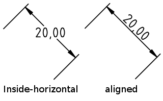
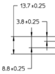
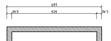
This is how an architectural dimension looks like:


dellus
Reply | Threaded
Open this post in threaded view
|

Re: Inside-horizontal dimensions

sankey
See https://github.com/LibreCAD/LibreCAD/pull/975

Also, would you be able to do additional testing?
Reply | Threaded
Open this post in threaded view
|

Re: Inside-horizontal dimensions

LordOfBikes
Administrator
Merged!

I tested a LibreCAD DXF for reference with DWG TrueView and got same results.

Thanks to you both for battling this down

Armin
investing less than half an hour into Search function can save hours or days of waiting for a solution
Reply | Threaded
Open this post in threaded view
|

Re: Inside-horizontal dimensions

dellus
In reply to this post by sankey
Wow, sankey, many thanks and blessings for this, you are my darling! This issue has annoyed me all the time. Could not  test yet, the nightly is not yet available.

dellus
Reply | Threaded
Open this post in threaded view
|

Re: Inside-horizontal dimensions

sankey
FWIW, I was doing some testing of LibreCAD DXF files with Autodesk Viewer (viewer.autodesk.com), and noticed that general scaling influenced fixed extension lines.  So, we can be quite sure that Autodesk wants this to be true, even if they did not write it explicitly :)
Reply | Threaded
Open this post in threaded view
|

Re: Inside-horizontal dimensions

dellus
This post was updated on .
Tested now, works. Wondered how existing drawings with fixed extension lines made in the old version would open. I had a faint hope the values would somehow be automatically adapted to the new system, but nope. So old drawings will have to be adapted manually, no biggie, but users will have to know it. The cleanness of the new handling is well worth this inconvenience.
But while testing old drawings I ran into a problem: In an architectural drawing with scale 1:100 and units set to m (standard in Germany) I couldn't set the fixed extension line small enough, as the input mask only accepts two digits after the decimal point. So it's a problem of the user interface. Maybe this is not within your expertise, sankey. Somebody else able and willing?
While testing an idea flashed up: wouldn't it make sense to submit normal text also to general scale? This of course would require a much greater effort, adapting the user interface. I'm not asking you to do this, just a thought, maybe for a future release.

dellus      
Reply | Threaded
Open this post in threaded view
|

Re: Inside-horizontal dimensions

dellus
In reply to this post by sankey
Hello sankey,
I had expected a comment by you on my last posting. Now I fear I might have offended you unintentionally. When calling for someone else able and willing, I didn't mean you were unable and unwilling. I just wanted to take any pressure from you to have to do it. I'm glad for what you have done.
If you don't have the knowledge, time or are not in the mood for it, that's absolutely o.k.
Though it would be a pity if your improvement had to be withdrawn, because it doesn't work for all conditions. But who knows, maybe you are secretly working on a solution? Please give a statement.
Concerning the "autocorrection", I had imagined the size of the extension lines and the other dimension components are written in the dxf-file as they are really drawn and printed, and the values in the settings tab are just a way to define this. So when the settings tab structure is changed the values in there would change automatically. But I'm not a coder and don't know how these things work.

dellus
Reply | Threaded
Open this post in threaded view
|

Re: Inside-horizontal dimensions

sankey
dellus wrote
Hello sankey,
I had expected a comment by you on my last posting. Now I fear I might have offended you unintentionally. When calling for someone else able and willing, I didn't mean you were unable and unwilling. I just wanted to take any pressure from you to have to do it. I'm glad for what you have done.
If you don't have the knowledge, time or are not in the mood for it, that's absolutely o.k.
Though it would be a pity if your improvement had to be withdrawn, because it doesn't work for all conditions. But who knows, maybe you are secretly working on a solution? Please give a statement.
Concerning the "autocorrection", I had imagined the size of the extension lines and the other dimension components are written in the dxf-file as they are really drawn and printed, and the values in the settings tab are just a way to define this. So when the settings tab structure is changed the values in there would change automatically. But I'm not a coder and don't know how these things work.

dellus
Not to worry at all!  I am consumed by other work at the moment.  In fact, if you are looking at this, LordOfBikes, you maybe should not wait for any more of my contributions before releasing librecad 2.2.0, since it could be months before I continue this dimensions work.